This document is an Installation, Operation & Maintenance Manual for Duff-Norton Electromechanical Linear Actuators, specifically the 6415 and 7415 Series AC models (115 Volt A.C./220 Volt A.C.).
Function Description
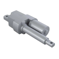
The Duff-Norton 6415 & 7415 Series AC actuators are electromechanical linear actuators designed for industrial use. Their primary function is to provide linear motion, typically for lifting, pushing, pulling, or positioning applications. The actuators are equipped with an enclosed, permanent split capacitor induction type AC motor. A key feature is the integrated thermal overload protection, which automatically opens and resets to prevent motor damage. The actuators also incorporate a preset brake mechanism at the factory, which is crucial for preventing self-lowering of the actuator under load. Limit switches are included to define and control the stroke limits, ensuring safe operation within specified parameters. For enhanced control and feedback, some units can be equipped with a potentiometer for position indication and a digital position indicator (Duff-Norton part no. SK6300-4K) for precise digital readout of actuator position.
Important Technical Specifications
General Actuator Characteristics:
- Motor Type: Enclosed, permanent split capacitor induction type AC motor.
- Voltage Options: 115 Volt A.C. or 220 Volt A.C.
- Thermal Overload: Automatically opens and resets.
- Brake: Factory preset, prevents self-lowering.
- Lubrication: Pre-lubricated at the factory, requiring minimum maintenance.
- Limit Switches: Checked at the factory for proper functioning; adjustable.
- Load/No-load Speeds: Approximately equal.
6415 Series DC Actuator Specifications (Table 1-1):
- Applied Load (lbs): 500, 1000, 1500
- Speed (in./min) - Standard 115 Volt Motor (60 Hz): 52, 51, 50
- Speed (in./min) - Standard 220 Volt Motor (50 Hz): 44, 42, 41
- Amps - Standard 115 Volt Motor (60 Hz): 5.00, 5.50, 6.20
- Amps - Standard 220 Volt Motor (50 Hz): 1.70, 1.70, 2.00
6415 Series DC Super Pac Actuator Duty Cycle (Table 1-2):
- Applied Load (lbs): 500, 1000, 1500
- # Duty Cycle (in/hour) - Standard 115 Volt Motor (60 Hz): 560, 540, 500
- # Duty Cycle (in/hour) - Standard 220 Volt Motor (50 Hz): 675, 625, 600
- Note: "# Total inches of travel (up and down) per hour with equally timed intervals between cycles."
Potentiometer Specifications (Table 5-1):
- Travel 9 in or less: Potentiometer (26a) SK-3275-24, 5000 Ohms, 530 Ohms/Inch Change. Potentiometer with gear (26) SK-6415-70-10A.
- Travel Over 9 in: Potentiometer (26a) SK-6200-18, 5000 Ohms, 167 Ohms/Inch Change. Potentiometer with gear (26) SK-6415-70-5A.
Dimensions (Figure 1-1):
- Various dimensions are provided, including overall length, clevis mount dimensions, translating tube diameter, and limit switch box dimensions. For example, the translating tube has an O.D. of 1.500 (+0.005, -0.000) inches. The overall length varies with travel, e.g., Travel + 12.25 ± 0.13 inches (for travel over 3 inches) or Travel + 15.25 ± 0.13 inches (for travel of 3 inches or less) for one configuration, and Travel + 14.25 ± 0.13 inches (for travel of 3 inches or more) or Travel + 17.25 ± 0.13 inches (for travel of 3 inches or less) for another.
Usage Features
Industrial Use Only: These actuators are strictly intended for industrial applications. They should not be used to lift, support, or transport people unless specifically authorized in writing by Duff-Norton Company for such an application.
Installation:
- Wiring: Detailed wiring diagrams (Figure 1-2) are provided for connecting the actuator to the power source, including motor leads, capacitor, and limit switches. Wires are color-coded for direction of travel.
- Limit Switch Adjustment: Critical for safe operation. The manual provides step-by-step instructions for setting both the retracted and extended positions of the limit switches. This involves operating the actuator, rotating the translating tube, and adjusting limit switch nuts (B and C) to achieve desired travel. CAUTION: Power must be disconnected before making adjustments. Actuator should not be operated before setting limit switches.
- Potentiometer Installation (for units with this feature): Detailed steps are provided, including loosening the pot locknut, soldering leads, and carefully engaging the potentiometer shaft gear teeth with the plastic worm. Specific instructions are given for single-turn (travels up to 9 inches) and multi-turn (travels greater than 9 inches) potentiometers to ensure correct resistance settings for retracted and extended positions.
- Digital Position Indicator (SK6300-4K): This optional device provides a precise digital readout of actuator position, programmable for percentage, inches, or other units. It is self-calibrating. Wiring instructions for connecting potentiometer terminals (CCW, CW, S) to the indicator are provided.
- Air Vent Positioning: After installation, the air vent must be positioned to prevent moisture and dirt ingress. It can be repositioned by loosening a set screw, rotating the outer air tube, and re-tightening. An elbow can be used for more effective positioning.
Operation:
- Intermittent Duty Motor: The motor is designed for intermittent duty. Continuous running for approximately 10 minutes, regardless of load, will cause the thermal overload relay to cut out. It then takes about 10 minutes for the motor to cool sufficiently for the relay to reset. Users must ensure the duty cycle is not too severe.
- Power Supply: Low voltage supply should be avoided. All wiring and switches must be adequately sized for the required current.
- Alignment: Clevis pins should be parallel to prevent binding during pivoting.
- Braking: The preset brake provides consistent braking. If excessive drift occurs due to worn friction surfaces, the brake will require rebuilding (repair kit SK-6415-41 is available).
- Jamming Warning: The actuator is not recommended for applications where it can be jammed (e.g., overtraveling limit switches, jamming nut and screw internally, or driving against immovable objects). While it can withstand a limited number of jams without damage, Duff-Norton Engineering should be consulted if jamming is expected.
- Temperature Warning: Actuator external surface temperatures may reach 230°F at or near maximum allowable duty cycle.
Maintenance Features
Lubrication:
- Duff-Norton recommends Exxon Ronnex Extra Duty #1 for proper lubrication.
- The translating tube (66) should be filled approximately 1/2 to 3/4 full with Duboise M.P.G. grease (no substitutes) during assembly.
- The housing (42) gear box cavity should be packed with Aeroshell #6 grease (no substitutes) during assembly.
- The O.D. of the spring (49) and pocket of the insert (51) should be greased with Aeroshell #6 grease during brake assembly.
- A generous amount of Aeroshell #6 grease (no substitutes) should be applied to thrust washers (35) and thrust bearing (36) during assembly.
Required Tools:
- Bearing puller
- Press
- Soft jaw table clamp
- Common hand tools
General Procedures for Disassembly and Assembly:
- Tagging: Critical parts should be tagged to facilitate reassembly.
- Marking: Mating surfaces should be marked to ensure proper meshing.
- Cleaning and Lubrication: Parts should be cleaned and lubricated as required.
- Seals: All seals must be replaced if damaged during a rebuild.
- Fasteners: All screws, washers, and other small common parts must be replaced if mutilated.
- Disassembly should be performed on a clean cloth.
Detailed Disassembly and Assembly Steps:
The manual provides an extensive, numbered list of steps for complete disassembly and reassembly of the actuator, referencing an exploded parts illustration (Figure 5-1) and specific part numbers (Table 5-1). Key steps include:
- Removing covers, gaskets, and insulation.
- Disconnecting and removing the capacitor.
- Disconnecting and routing motor and switch lead wires.
- Removing the motor, thrust washers, and bearings.
- Disassembling the limit switch shaft, nuts, and worm.
- Removing the outer tube, air vent, wiper scraper, and guide bushing.
- Disassembling the spacer nut from the screw.
- Removing output gear, key, and associated components.
- Separating the translating tube from the lifting nut by driving out pins.
- Removing the lifting screw from the lifting nut.
- Removing the brake assembly (if necessary), which involves removing a spring, insert, retaining ring, input pinion, and bearing.
- Reassembly instructions are provided in reverse order, with specific notes on proper alignment, lubrication, and tightening procedures. For example, care must be taken not to damage the potentiometer during gear assembly, and the input pinion and motor shaft flats must be opposite each other for correct coupling alignment.
- Specific instructions are given for assembling the limit switch bracket, insulation, switches, shaft, nuts, and worm, ensuring correct orientation and wiring.
- Final adjustments include setting the limit switches and, if applicable, calibrating the potentiometer.
Parts List (Table 5-1):
A comprehensive parts list is provided, detailing each component by index number, part name, quantity required, and part number. This is essential for ordering replacement parts. It also includes specific part numbers for 115V and 220V capacitors and motors, as well as potentiometer assemblies for different travel lengths.
Technical Illustrations (Section VI):
- Brake Alignment (Figures 6-1A, 6-1B): Diagrams illustrate the correct alignment of the pinion coupling, motor coupling, and brake spring.
- Limit Switch Wiring Diagram (Figure 6-2): A detailed schematic showing connections for the motor, capacitor, AC line, and limit switches (SPDT type), including wire colors and cam switch functions (CW/CCW).
- Limit Switch Assembly (Figure 6-3): An exploded view showing the components of the limit switch assembly, including the nut restrainer (A), limit switch nuts (B and C), switches, insulation, and wiring connections, along with motor lead wire identification.
Warranty:
Duff-Norton warrants parts to be free from defects in material and workmanship for one year from the date of shipment. The warranty covers repair or replacement of defective parts but excludes damage due to improper maintenance, eccentric loading, overloading, chemical or abrasive action, excessive heat, or other abuse. Alterations or modifications without authorization void the warranty. The warranty for non-Duff-Norton manufactured accessories is limited to the manufacturer's warranty.