03-TM-0038 REV 00 PAGE 2 OF 5
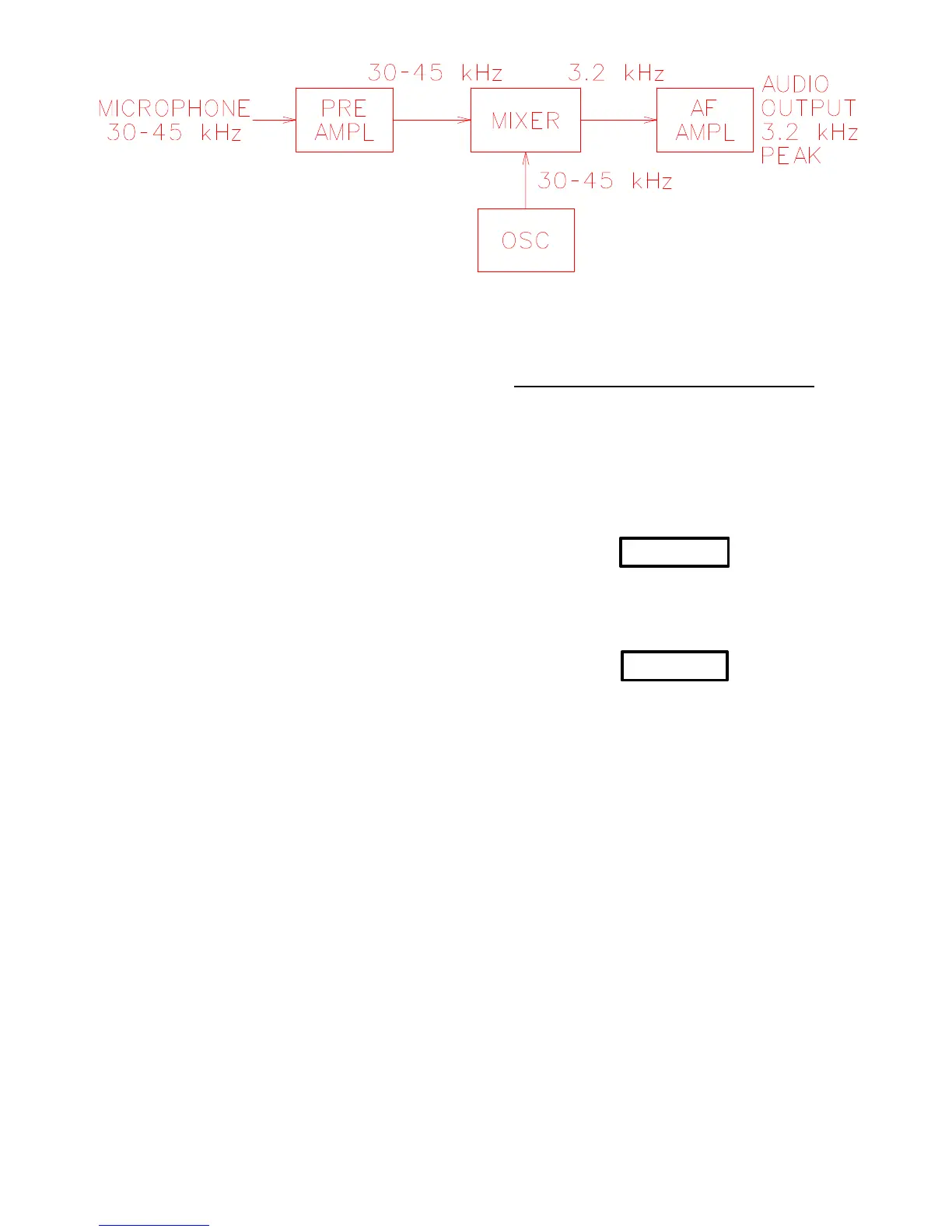
Figure 1.2. Test Set Block Diagram.
1.2.3. BLOCK DIAGRAM. Figure 1.2. is a block diagram
and Figure 3.1. is the schematic diagram of the test set. The
microphone detects a beacon signal which is amplified and
fed into the mixer. The tunable oscillator frequency is also
fed into the mixer. When tuned above or below the incom-
ing signal, the difference frequency is the resultant output
from the mixer, and will be in the audio range when the dif-
ference is within 1000 to 3000 Hz. When both frequencies
are the same, the difference frequency is zero, hence no out-
put from the mixer. The signals coming out of the mixer are
amplified by the audio amplifier, where most of the gain of
the test set is provided.
1.3.1 AUDIO OUTPUT.
1.3. AUXILIARY CONNECTIONS AND USES
A. The test set AUDIO OUTPUT jack circuit is designed to
work into a load impedance of approximately 10 ohms
which is ideal for attachment of low impedance head phones.
Operation into higher impedance such as oscilloscopes, me-
ters, chart recorders or other types of readout equipment is
permissible. No DC potential is present on the AUDIO
OUTPUT jack.
CAUTION
A SHORT ACROSS THE AUDIO OUTPUT
JACK MAY CAUSE DAMAGE TO THE TEST
SET CIRCUITRY.
CAUTION
TEST SET IS NOT WATER-PROOF OR
SPLASH PROOF. SOME FORM OF
PROTECTION SHOULD BE PRO-VIDED
WHERE SPLASH CONDITIONS EXIST.