7
RFDU Operator’s Manual
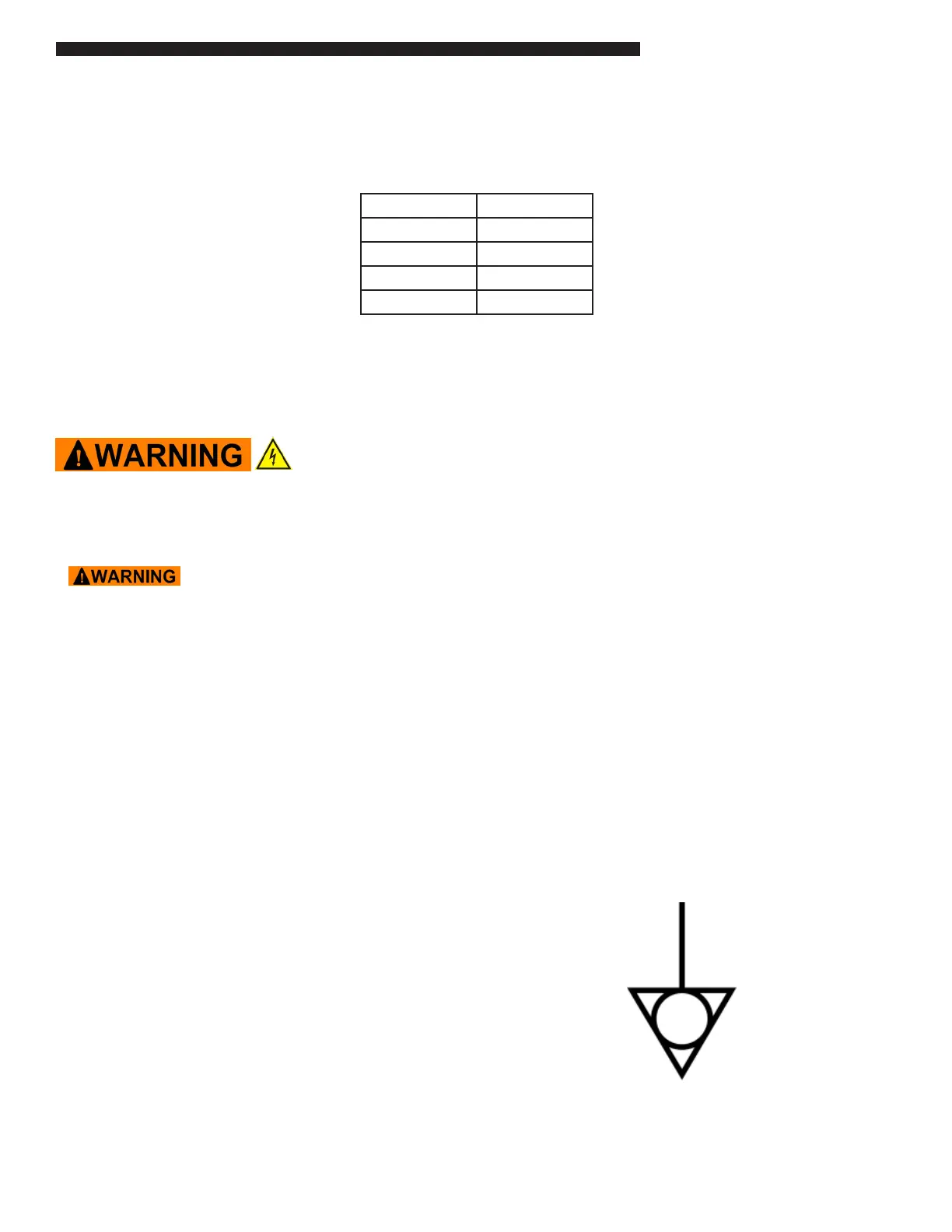
The following minimum clearances must be maintained between the warmer and any combustible or non-
combustible substance:
Proper airow around unit will cool the electrical components. With restricted airow, the unit may not
operate properly and the life of the electrical components may be reduced. A 2” clearance is recommended
at the control side for longer control life expectancy.
ELECTRICAL SHOCK HAZARD UNIT MUST BE SAFETY GROUNDED, EARTHED.
DO NOT MODIFY, DEFEAT ELECTRICAL CONNECTIONS.
ELECTRICAL CONNECTIONS
BEFORE CONNECTING THE UNIT TO THE POWER SOURCE, VERIFY THAT THE
VOLTAGE AND PHASE OF THE POWER SOURCE ARE IDENTICAL TO THE VOLTAGE AND
PHASE INFORMATION ON THE DATA LABEL.
EARTHING INSTRUCTIONS
Connection of the unit to the mains supply MUST be performed by an authorized person in accordance
with codes, standards, and laws governing the installation site using properly rated all poles mains
protection, all poles mains disconnects, safety ground earthing, and shall be a minimum of 48” (1.2 meter)
long to allow the equipment to be moved for cleaning.
USA and non-EU Countries must use exible conduit within variances that may be required by local electric
codes or regulations. European Union (CE) installations must use HO7RN-F, 5G 2,5mm exible cordage.
The Mains Supply safety / earth ground wire must be longer than mains conductors at the unit’s
interconnections to prevent stress under pull.
EXTERNAL EQUIPOTENTIAL
Terminal provides a connection for bonding to equipment enclosure.
Unit Clearance
Right Side 2”
Left Side 2”
Rear OPEN
Floor 0”
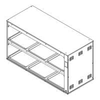
INSTALLATION