Do you have a question about the dunkermotoren BG 65 SI and is the answer not in the manual?
Introduces the EC-motors (brushless DC motors) with integrated speed control electronic for 4-quadrant operation.
Provides definitions for technical terms like Bridge rectifier, Smoothing capacitor, Hall sensors, Index impuls, Ramps, CAN-Monitor.
Details guidelines for installing and operating the BG 65 SI motor in industrial machinery and equipment.
Outlines EU guidelines, machine guideline, EMC guideline, and conformity for the drive.
Lists electrical specifications such as maximum motor speed, voltage, current, and ripple.
Details mechanical specifications like temperature range, humidity, protection class, and connector type.
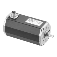
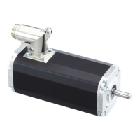
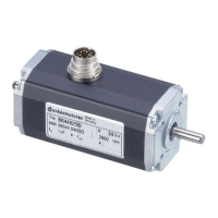
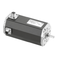
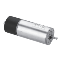
Provides dimensional drawings and specifications for the motor.
Presents technical data for the BG 65x25 SI motor model.
Presents technical data for the BG 65x50 SI motor model.
Presents technical data for the BG 65x75 SI motor model.
Lists available accessories like incremental transmitters, worm gears, planetary gears, and brakes.
Explains the function of the ballast circuit for handling kinetic energy during braking operations.
Details the motor's over-temperature protection mechanism and error reporting.
Provides guidance on securely fastening the drive to a flat surface and handling the motor drive shaft.
Addresses electromagnetic radiated interferences and their impact on system safety.
Explains the importance of earthing the motor housing to protect against static discharge (ESD).
Discusses standard 12-pole connectors and alternative connection options.
Details the 12-pin drive connector for motor and electronic supply.
Provides wiring diagrams for connecting 24 V motors, showing signals and supply.
Provides wiring diagrams for connecting 42 V motors, showing signals, power, and logic supply.
Details pin assignments, functions, and strand colors for 24V motor connections.
Details pin assignments, functions, and strand colors for 42V motor connections.
Illustrates the schematic circuit for digital outputs OUT1, OUT2, and OUT3.
Illustrates the schematic circuit for digital inputs IN1, IN2, IN3, and IN4.
Specifies maximum cable lengths and considerations for common 24V DC power sources.
Shows the schematic circuit for power supply and controller/motor connection, including soft start.
Provides instructions for initial motor operation, connection of voltage, and control inputs.
Explains how digital inputs IN1 and IN2 control four operating conditions: stop, counter-clockwise, clockwise, and stop with holding torque.
Describes how digital inputs IN3 and IN4 enable teaching of fixed speed values and switching between regulated/unregulated modes.
Details the step-by-step procedure for teaching and storing fixed speed values using digital inputs.
Explains how to adjust and teach acceleration and braking ramp times using analogue input and digital inputs.
Describes the pulse output OUT1, providing 15 impulses per motor turn for speed measurement.
Details protective functions like over-temperature and undervoltage, and how fault output OUT3 signals them.
Explains the analogue input circuit for setting motor speed via voltage input (0-10V).
Warns about wear and voltage peaks with attached brakes and recommends using a free-wheeling diode.
Describes the factory quality mode (Q mode) testing procedure before delivery.
States the drive requires no maintenance and provides instructions for disposal and fault handling.
Provides contact information for sales, technical support, and online resources.
Indicates that scope of delivery is 'As quoted'.
Provides the URL for downloading PDF manuals.
Contains the CE Declaration of Conformity and lists applied standards and safety warnings.
| Brand | dunkermotoren |
|---|---|
| Model | BG 65 SI |
| Category | Engine |
| Language | English |