6
2.ToattachthePTTtoaflatsurface,removethe2screwsfromthe
bottomofthePTT,whichholdstheVelcrostripinplace.Removethe
stripsandreplacethesmallplasticpartthatheldthestripsinplacewith
thelargerflatplasticpartsuppliedwiththePTT.Screwth
enewplastic
partinplace.
3.Feed thecableoutofsighttothelocationwhereyouintendtomount
thejunctionbox.
Caution:Makesurethereissufficientslackinthecabletoallowthefree
movementofthegearleverwithoutstretchingthePTTcable.
D.InstallingthePowerCable
Caution! The Car kit should be used with a negative ground electrical
system only. Reverse polarity (positive ground) will trigger protection
circuits which cause the cable fuse to open. Check the ground polarity
beforeyoubegintheinstallationtopreventwastedtimeandeffort.12V
DCor24VDCautomotivesystemsaredire
ctlysupported.Determinethe
best cable route to the vehicle ignition for the Power Cable from the
locationwhereyouintendtomounttheJunctionBox.
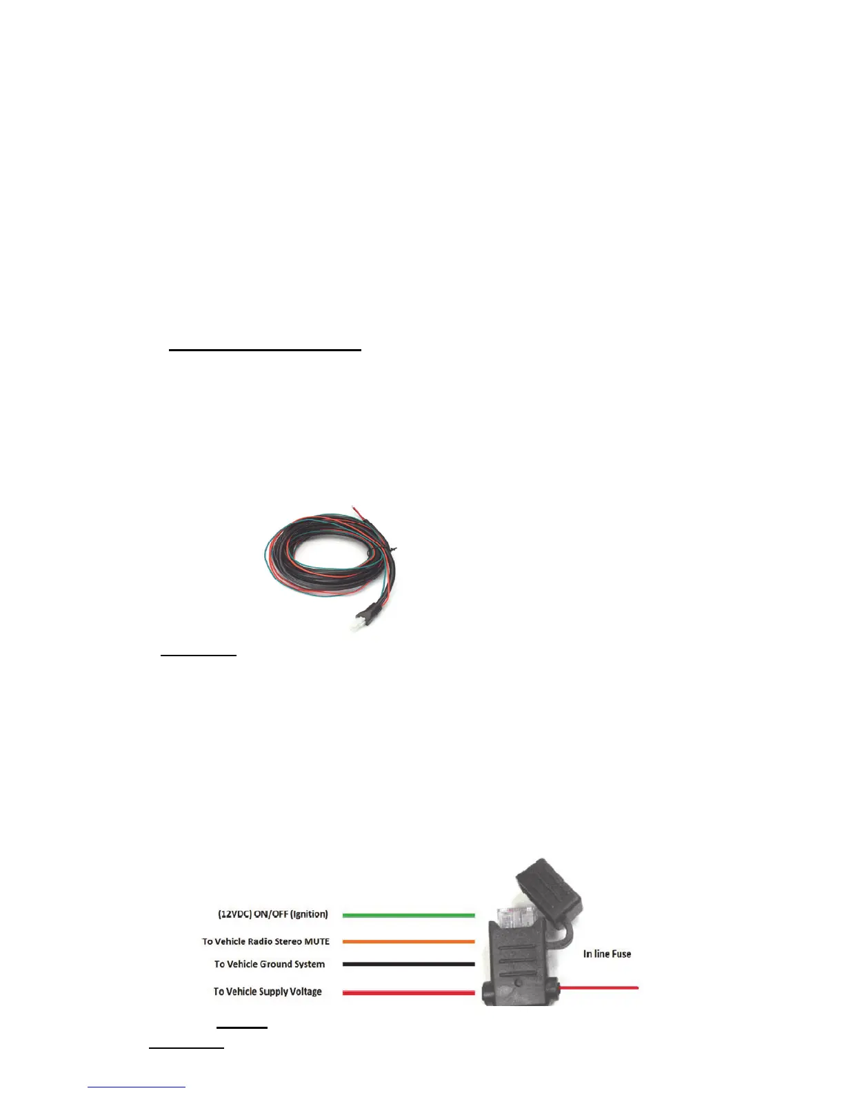
Diagram4
1.Route theblackleadof themainpowercabletoaconvenientchassis
groundandtheredleadtothepositivesupplyvoltageconnectionpoint.
Ifitisnecessarytopenetratethefirewall,trytouseanexistingopening.
2.Ifthereisnoexistingopening,drillanewho
leapproximately9/16”or
3.5cmindiameter.Makesurethatthereisclearanceontheoppositeside.
Insert a grommet into the hole to prevent damage to the power cable.
When makingconnections on the engine side of the firewall, additional
in‐linefuseholder(included)shouldbeusedattheco
nnectionpoints.
GREEN MUST
GO TO IGNITION OR CONNECTED WITH RED
Diagram5
 Loading...