How Your 9100SXT Downflow Water Conditioner Works
Hard water enters your home through the main supply line, enters the softener and passes down through a resin mineral
bed which softens the water. An ion exchange process takes place in which the resin beads capture and hold calcium and
magnesium, the hardness minerals, while the water takes on sodium ions. The soft water then flows into your household
water line.
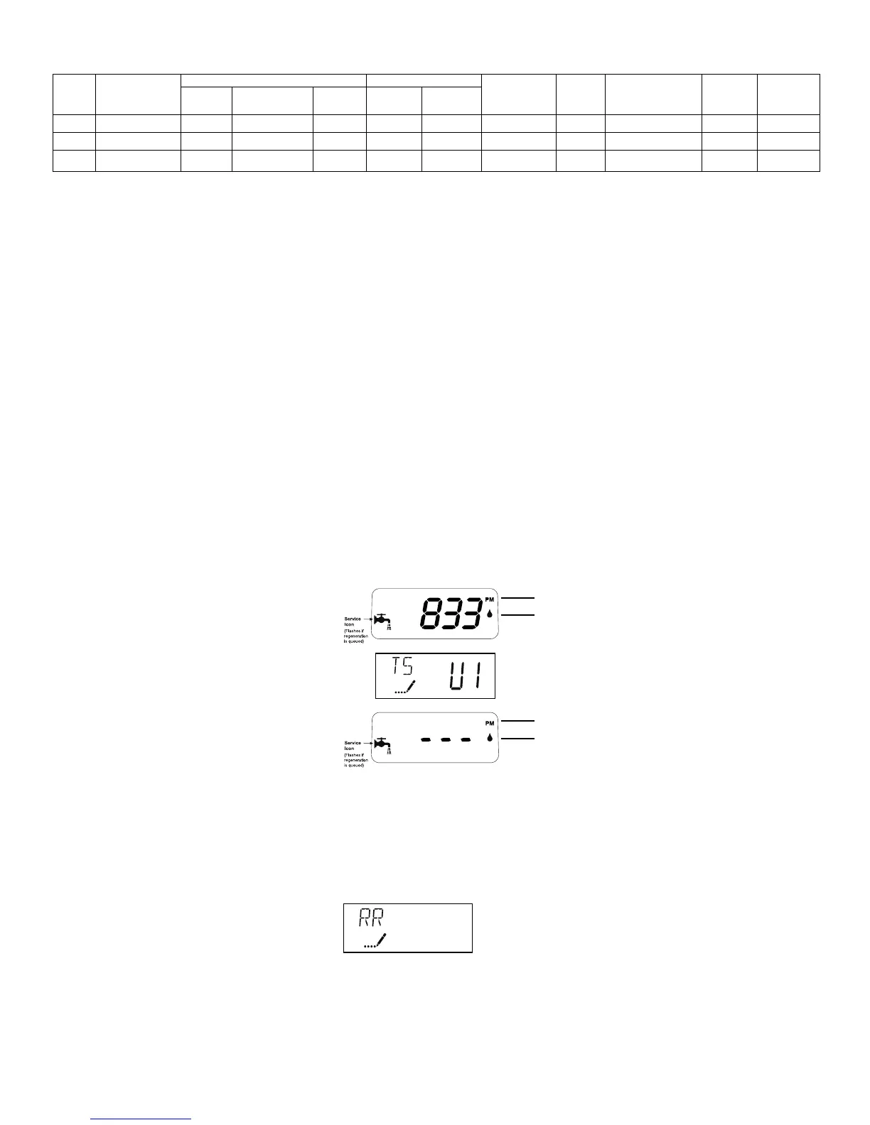
In normal operation, the Time of Day display will alternate being viewed with the Volume Remaining display then the Tank
in Service. This display will be in gallons, liters or cubic meters. The tank in service will be shown as U-I or U-2. As treated
water is used, the Volume Remaining display will count down from a maximum value to zero or (---).Once this occurs, a
regeneration cycle will be initiated at the Set Regeneration Time. Water flow through the valve is indicated by the Flow
Indicator that will flash in direct relationship to flow rate.
Example 833 Gallons of Treated
Water Remaining
Tank In Service
0 Gallons of Treated
Water Remaining
Control Operation During Regeneration
In regeneration, the control will display a special regeneration display. In this display, the control will show the current
regeneration step number the valve is advancing to or has reached and the time remaining in that step. The step
number displayed will flash until the valve has completed driving into this regeneration step position. Once all
regeneration steps have been completed, the valve will return to Service and resume normal operation.
Example Less than 6 minutes
remaining in Regen
Step Rapid Rinse
Pushing the Extra Cycle Button during a regeneration cycle will immediately advance the valve to the next cycle step
position and resume normal step timing.
1
Performance
PM Indicator
Flow Indicator
(Flashing with water flow)
PM Indicator
Flow Indicator
(Flashing with water flow)
*Items include brine tank grid
Maximum Water Temperature = 110°F (43°C)
Maximum Operating Pressure = 100 PSIG (689 kPa)
Voltage = 110 volts standard
Pipe Size = 3/4”
• Capacities are based on two tanks of resin. Eg: DT30TM, 9100SXT
set at 6lb/cf selt setting would provide 23,000 grains of hardness
removal for one tank.
• At the stated service flow rates, the pressure drop through these
devices will not exceed 15 psig.
• Changing salt settings from factory setting may require changing
injector sizes to achieve stated capacities.
• Do not use where water is microbiologically unsafe.
• The manufacturer reserves the right to make product improvements
which may deviate from the specifications and descriptions stated
herein, without obligation to change previously manufactured products
or to note the change.
Capacity Grains Flow Rate Mineral Resin Cabinet/Brine Salt Shipping
Part Model @ 10 lbs Factory set @ @ 3 lbs Service Backwash Tank Size Volume Tank Size Capacity Weight
No. No. per cu ft 6 lbs per cu ft per cu ft USGPM USGPM Inches Cu Ft Inches W x D X H Lbs Lbs
6217 DT30TM, 9100SE 60,000 46,000 32,000 10 2 10 x 35 2 18 x 35 224 195
6218 DT40TM, 9100SE* 75,000 57,500 40,000 11 2 10 x 47 2.5 21 x 36 308 221
6219 DT45TM, 9100SE* 90,000 69,000 48,000 14 2 10 x 54 3 21 x 36 308 320
 Loading...