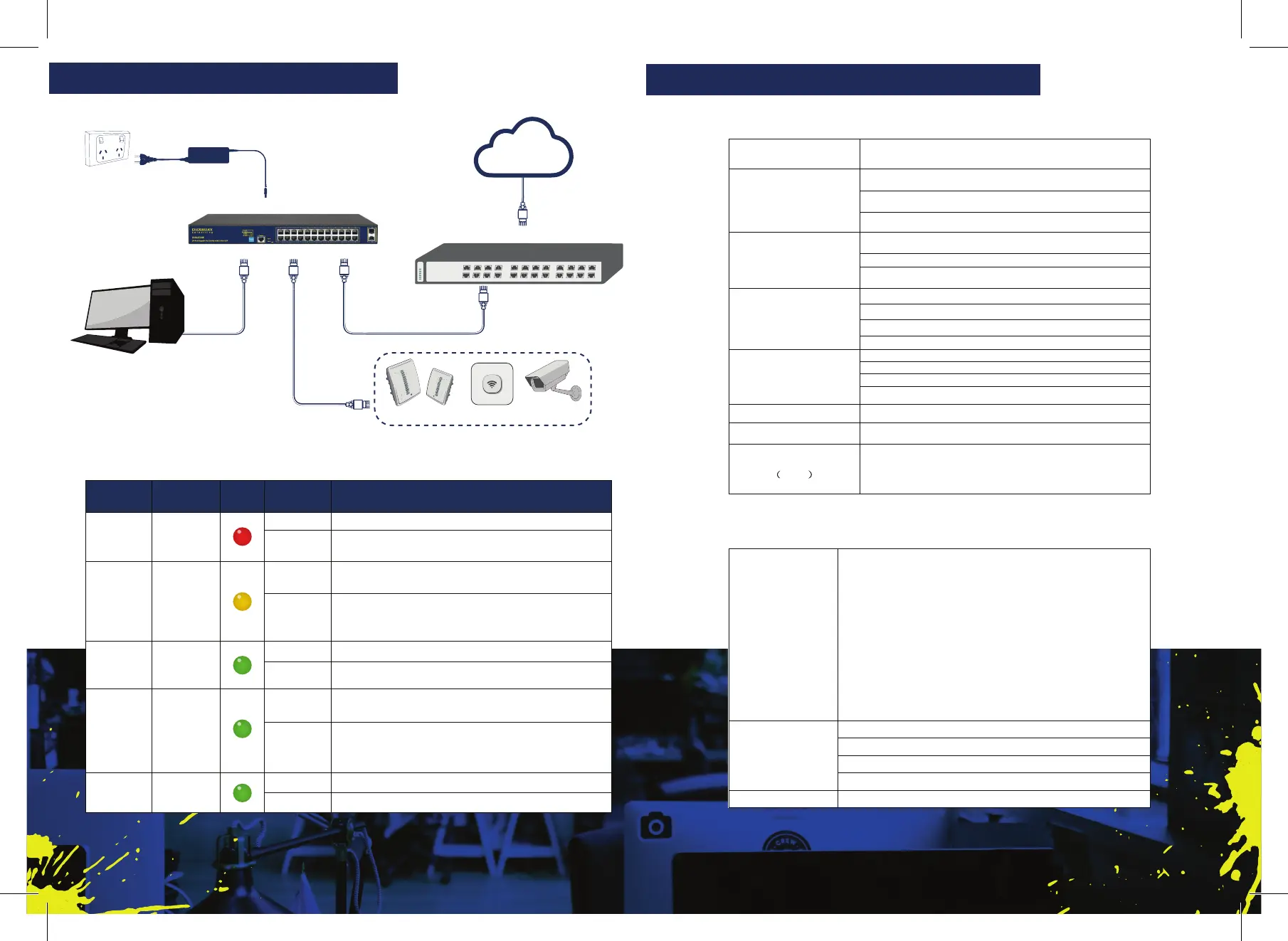
Internet
Power
24-Port Gigabit Switch
PD
PC
Bridge IP-CameraAP
INSTALLATION DIAGRAM
Link/
Act
Indicator
INTERFACE FUNCTION LIST
Indicator
s
Title Color
Descripon
POWER
Power
indicator
O
No power, the power switch is not turned on,
power supply is abnormal
POE
POE
power
indicator
Solid
The corresponding RJ45 port is connected to the
powered device and the power supply is normal
O
The corresponding RJ45 port is not connected to
the powered device or the power supply is
LINK/ACT
on
Blinking A valid link is established
O An invalid link is established
SYS
System
indicator
Blinking
System is funconing properly
O
System is funconing improperly Soware is
damaged
9-10
SFP
indicator
A valid link is established on the SFP port
An invalid link is established on the SFP port
4.2 Soware Specicaons
Protocol Standard
IEEE 802.3:Ethernet Media Access Control ( MAC) Protocol
IEEE 802.3i:10BASE -T Ethernet
IEEE 802.3u:100BASE -TX Fast Ethernet
IEEE 802.3ab:1000BASE -T Gigabit Ethernet
IEEE 802.3z:1000BASE -X Gigabit Ethernet (ber)
IEEE 802.3ad:Standard method for performing link aggregaon
IEEE 802.3x:ow control
IEEE 802.1p:LAN Layer 2 Qos/Cos protocol for trac priority (mulcast ltering)
IEEE 802.1q:VLAN
IEEE 802.1d:STP Spanning tree
IEEE 802.1s:MSTP Spanning tree
IEE
E 802.1w:RSTP Spanning tree
IEEE 802.3af
IEEE 802.3at
Shortcut Funcon
One key CCTV(1-8 port 250meters PoE distance)
One key Q0S (Video priority)
Network standard
IEEE 802.3i IEEE 802.3u IEEE 802.3x
IEEE 802.3ab IEEE 802.3af IEEE 802.3at
Port
24 10/100/1000Mbps RJ45 port
PoE
24 10/100/1000Mbps RJ45 port support PoE+
LEDs
Performance
Forwarding mode: store and forward
:
:
Lightning protecon
Input
Dimension
(
L×W×H)
440mm×180mm×44mm
 Loading...