10 Instruction Manual Water Softener IV
ENGLISH
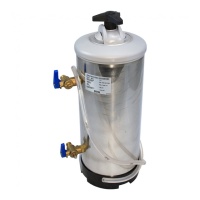
instruction manual
Water Softener IV
Room temperature: ....... 4°C - 35°C
Joints for the connection to the water system: 3/8”G; 3/4”G (fig. 3)
2.5 CHARACTERISTICS OF FEED WATER
Feed water must be:
• Drinkable and clean (SDI 1)
• Temperature must be between 6° and 25°C
• Hardness must be below 900 ppm CaCO
3
(90°f)
2.6 EQUIPMENT PERFORMANCE BASED ON WATER
HARDNESS
3. INSTALLATION
3.1 PACKAGING
• Before the installation, check that the equipment was not
damaged by the transport and does not show any anomaly.
If in doubt, ask your seller, whose information is written on
the back of this manual.
• Don’t throw the package away for some time, being careful
to keep any dangerous or small parts of the package away
from children.
3.2 CHOOSING THE PLACE OF INSTALLATION
• Ensure that any other water treatment machine is not pre-
sent upline of the place of installation.
• Ensure that feed water comes from a drinking water pipe.
We recommend checking the chemical and physical para-
meters of the drinking water as well as its hardness before
installation.
• Install the equipment near a floor sink, to dispose of the
waste water produced by the regeneration.
• Install the equipment in a dry place that can be easily ac-
cessible to maintain, regenerate and clean the equipment.
Do not install the equipment in dirty and unhygienic places,
or in any place difficult to clean.
• Ensure that room temperature in the place of installation is
between 4°C and 35°C.
• Keep away from corrosive or acid products.
• Do not install in places where electric safety norms or per-
sonal safety norms are openly disregarded.
• Hydric pressure must not be under 0.1 Mpa (1 bar) or over
0.8 Mpa (8 bar). (We recommend at least 3 or 4 bar)
• If hydric pressure is over 8 bar, it is necessary to install a
pressure regulator.
• Salt packages or boxes must not be kept in humid places
or in direct contact with the floor: keep it, for example, on a
wooden pallet.
3.3 CONNECTION TO THE WATER SYSTEM (fig. 2)
The connection of the equipment to the water system must
be done according to all applicable norms, following the in-
structions of the manufacturer and qualified personnel.
During the installation use pipes, hoses, valves and com-
ponents which comply with the applicable Italian norm on
hygienic safety, the Ministerial Decree 174/2004. They must
be kept in their sealed package until the moment of instal-
lation to preserve their hygienic safety. It is forbidden to use
components that are not suitable for drinking water contact,
or components whose hygienic safety was compromised, as
they could corrupt the quality of treated water and the equi-
pment itself.
Check if there are hygienic security taps on the entrance
and exit of the equipment. Remove them only during this
phase and not before.
3.3.1 QUICK JOINTS
The pipes are connected to the valve by quick joints.
Connect the water inlet (fig. 2, A) and outlet (fig. 2, B) pipes
to the joints in the package, tightening them safely (fig. 1, A
and B).
To connect the joint to the valve it is necessary to insert it all
the way in (fig. 1, C). The metal inserts of the quick joint will
prevent the pipe from disconnection.
To disconnect the pipe it is necessary to depressurize the
tank, then press on the black ring that surrounds the pipe next
to the insertion, and extract the pipe (fig. 1, D).
Ensure that:
• The water inlet and outlet pipes (fig. 2, A and B) comply with
the norms on drinking water pipes.
• The water inlet pipe (fig. 2, A) has an internal diameter of at
least 7 mm.
• A water inlet tap (fig. 2, C) must be installed by the user
between the water system and the water softener, to ensure
that water flow can be interrupted in case of necessity.
• Install on the water outlet a check valve (fig. 2, D) (DVGW,
DIN 1988 T2) to protect the water softener from a reverse
flow of hot water that could cause damage.
• Install a tap to take a sample of the outlet water, to test its
hardness.
All pipes must be free, not crushed or constricted.
3.4 CONNECTION TO THE DRAIN SYSTEM
Waste water resulting from the regeneration is funnelled into
the floor sink by the flexible pipe (fig. 2, E) included in the
package.
Warning: keep the drain pipe suspended over and not
immersed in the water of the sink (fig. 2, L).
At the end of the installation, before opening the water
inlet tap (fig. 2, C), rinse the resins as explained in the
chapter “ACTIVATION AND INSTRUCTIONS FOR THE RE-
GENERATION”.
4. ACTIVATION AND INSTRUCTIONS
FOR THE REGENERATION
4.1 RINSING THE RESINS
Turn the valve handle on number 4, backwash mode (fig. 5).
Open the water inlet tap (fig. 2,C) and let the water flow throu-
20°f 30°f 40°f 50°f 60°f
11°d 16°d 22° d 28°d 33°d
200ppmCaCO
3
300ppmCaCO
3
400ppmCaCO
3
500ppmCaCO
3
600ppmCaCO
3
IV8 400 8 5,6 1
IV12 500 10 8,4 1,5
IV16 600 12,5 11,2 2
IV20 900 19 14 2,5
1680 1120 840 672 560
2520 1680 1260 1008 840
3360 2240 1680 1344 1120
4200 2800 2100 1680 1400
LITRES OF WATER SOFTENED, BASED ON HARDNESS
WEIGHT
[kg]
RESIN
[l]
SALT/RIG.
[kg]
h
[mm]
MODEL