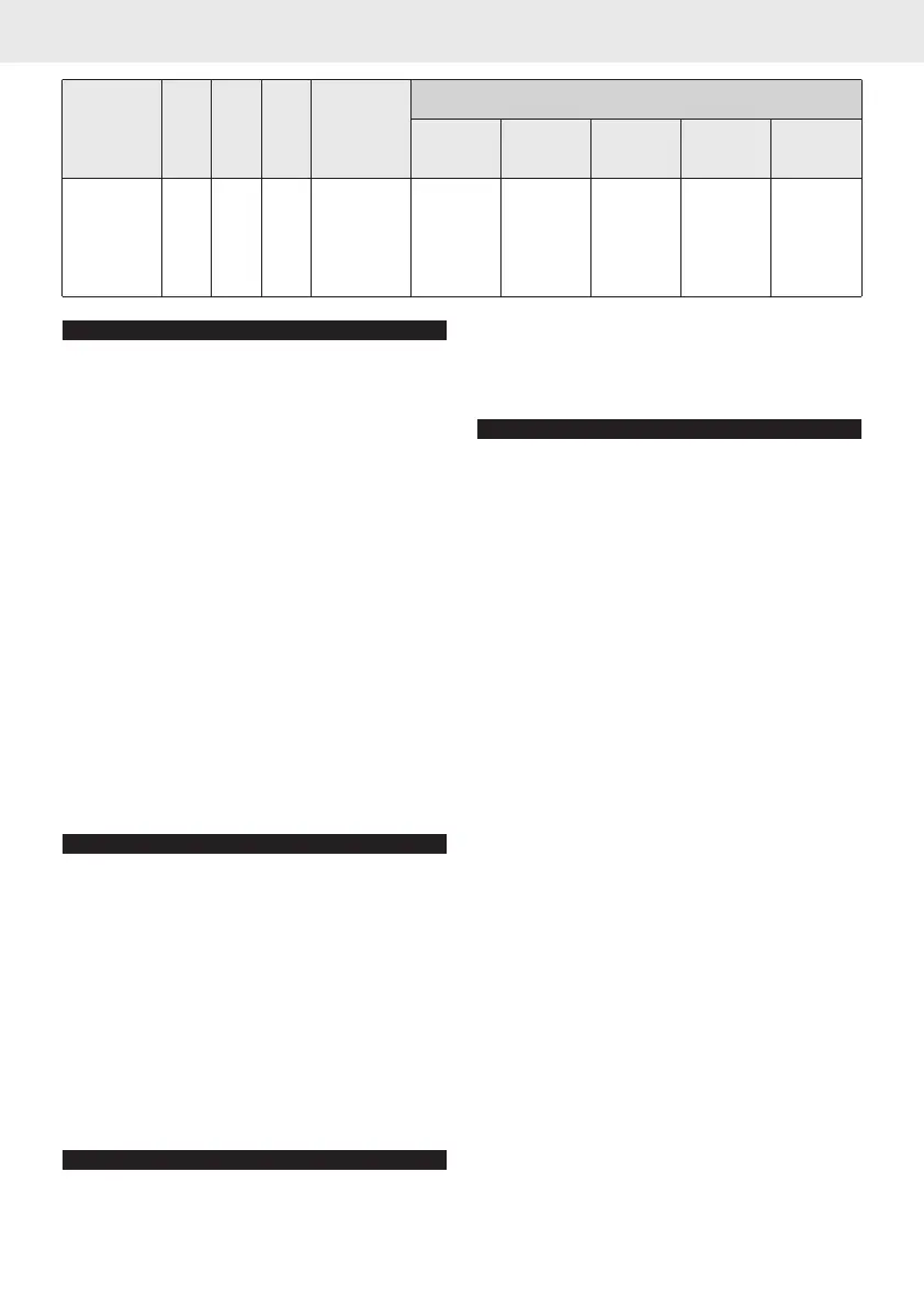
LT5 300 5 3,5 0,5
LT8 400 7,5 5,6 1
LT12 500 9,5 8,4 1,5
LT16 600 12 11,2 2
LT20 900 19 14 2,5
1050 700 525 420 350
1680 1120 840 672 560
2520 1680 1260 1008 840
3360 2240 1680 1344 1120
4200 2800 2100 1680 1400
TECHNICAL DATA
• Flow Rate 1000 l/h
• Minimum/Maximum Pressure 1 ÷ 8 bar
• Feed Water Min./Max. Temperature 4°C ÷ 25°C
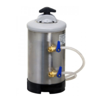
Figure 1 LEGEND
A Water Inlet E Pressure Relief Hose
B Water Outlet F Regeneration Hose
C Water Inlet Tap G Cover Knob
D Water Outlet Tap I Check Valve
This leaflet is an integral part of the product.
Please read the warnings provided carefully as
these provide important information concerning
the safe installation, use and servicing of this pro-
duct. This water softener is intended to be used to
soften cold drinking water only, any other use is
considered improper and as such unreasonable.
WARNING: use only sodium chloride NaCl in lar-
ge grains (kitchen salt) for regeneration. The use
of any other chemical substances or products is
strictly forbidden.
The resins in the water softener are needed
for this to work properly: please do not throw
them away.
INSTALLATION
• After removing the packaging, make sure that
the water softener isn’t damaged. Keep the
packaging materials (plastic bags, cardboard
box etc...) out of the reach of children as they
can be dangerous. The water softener should be
installed in full observance of the current laws,
following the manufacturer’s instructions and by
experts. If installed incorrectly, the equipment
may cause injuries to people and animals and
damage to property, in which case the manu-
facturer cannot be held liable.
• Install the water softener in rooms where the
temperature is between a minimum of 5 °C and
a maximum of 30 °C(Centigrade).
CONNECTION TO THE WATER MAINS (figure 1)
• The user must install a tap between the water
mains and the water softener so that the water
can be turned off in an emergency, plus a check
valve to avoid any pressure returns.
• Connect the water inlet and outlet hoses to the
water softener and make sure that these are ti-
ghtened properly.
• Place the drain hose directly in a drain.
COMMISSIONING
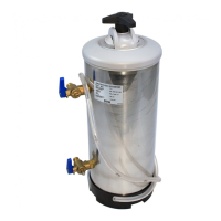
• RINSING OF RESINS (figure 2)
Place the outlet hose in a drain.
Turn the taps’ levers to the left and open the
water inlet; let the water flow until it is clear,
then stop the inlet water and connect the outlet
hose to the machine to be supplied.
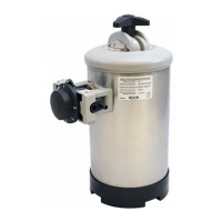
• ROUTINE REGENERATION (figure 3)
• position B
1) Place the depression hose in a bucket. Turn the
taps’ levers to the right and wait for the pres-
sure to drop. Remove the cover by unscrewing
the knob and then add the salt in the amount
indicated to suit the model (see table 1).
WARNING: Remove any salt from the seal on the
cover.
• position C
2) Return the cover and tighten the knob securely,
then move the inlet tap lever to the left.
WARNING: Remove any salt from the top of the
water softener.
3) Let the salty water flow from the drain hose
until the water is soft (about 40 minutes).
• position A
4) Return the water softener to normal working
conditions by turning the outlet tap lever to the
left.
5) Regeneration completed.
WARNING: the equipment connected to the
water softener is not supplied during regene-
ration.
To ensure the efficiency of the water softener at all
times, we recommend routine regeneration to suit
the use made of the water softener and the hard-
ness of the water used.
Please use the sheet printed on the last page to
keep a note of the dates when regeneration is
carried out.
4 Instruction leaflet and warnings for water softeners
ENGLISH Water Softener LT
20°f 30°f 40°f 50°f 60°f
11°d 16°d 22°d 28°d 33°d
200 ppm CaCO
3
300 ppm CaCO
3
400 ppm CaCO
3
500 ppm CaCO
3
600 ppm CaCO
3
LITERS OF WATER SOFTENED DEPENDING ON HARDNESS
WEI-
GHT
[kg]
RESINS
[l]
SALT/REG.
[kg]
h
[mm]
MODEL
 Loading...