11
English
Symbol Meaning
Do not dispose of the power
tool in a domestic waste
container�
DWT
power tool designation
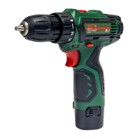
Cordless drills / screwdrivers are designed for hole
drilling in wood, plastic and metal, as well as for screw-
ing in and loosening of threaded fastening elements
(screws, bolts, etc�)�
1
Power tool
components
Keyless chuck
2 Torque regulator
3 Step speed selector switch
4 Ventilation slots
5 LED lamp
6 Indicators of the state of battery charge *
7 On / off switch
8 Reverse switch
9 Battery lock *
10 Battery *
11 Screwdriver bit *
12 Power unit *
13 Screw
14 Magnetic holder *
15 Indicator of the power unit *
* Optional extra
Not all of the accessories illustrated or described
are included as standard delivery.
Installation and regulation
of power tool elements
Before execution of any procedures, centre the re-
verse switch 8.
Do not draw up the fastening elements
too tight to avoid damaging the thread�
Mounting / replacement of accessories (see g. 1)
With long-term use the drill bit may be-
come very warm; use gloves to remove
it.
• Open the jaws of the keyless chuck 1, rotating its
front part as shown in gure 1.
• Mount / replace the accessory�
• Tighten the keyless chuck 1 without skewing the ac-
cessory as it is shown in gure 1.
Mounting / dismounting of the keyless chuck (see
g. 2-3)
• To mount the keyless chuck 1, carry out the opera-
tions in consecutive stages as it is shown in gure 2.
• To dismount the keyless chuck 1, carry out the oper-
ations in consecutive stages as it is shown in gure 3.
Attention: keep in mind that in the pro-
cess of mounting / dismounting of the
keyless chuck 1 the screw 13 has a left-
hand thread.
Screwdriver bit / magnetic holder (see g. 4)
For short screwdriver bits 11 (length 25 mm) use
the magnetic holder 14 for their reliable fixing (see
fig� 4)� A magnetic holder 14 is not needed for
extended screwdriver bits 11 (length 50 mm)�
Charging procedure
of the power tool battery
Initial operating of the power tool
The power tool is supplied with a partially charged
battery 10. Before the rst use, the battery 10 must
be fully charged.
Charging process (see g. 5)
• Centre the reverse switch 8�
• Press the two battery locks 9 and remove the bat-
tery 10 (see g. 5.1).
• Connect the power unit 12 to the power supply� Indi-
cator 15 will glow green�
• Insert plug of the power unit 12 in socket of the bat-
tery 10 (see g. 5.2).
• During charging the indicator 15 will glow red� When
charging is complete, indicator 15 will glow green�
• Disconnect the power unit 12 from the battery 10
and mount battery 10 in the power tool (see g. 5.3).
• Disconnect the power unit 12 from power supply�
Switching the power
tool on / off
Make sure that the reverse switch 8 is not centred,
this blocks on / off switch 7.
Switching on:
Press on / off switch 7.
Switching off:
Release the on / off switch 7�
Design features
of the power tool
Battery
The battery 10 is protected by the safety system
against deep discharge� In case of complete dis-
charge, the power tool is automatically switched off�
Attention: do not try to switch on the power tool
when the protection system is activated the bat-
tery 10 can be damaged.
Temperature protection
The temperature protection system enables to auto-
matically deactivate the power tool in case of excess
load or when the temperature of the battery 10 is ex-
ceeding 80°C� The system guarantees protection of
 Loading...