the TIMEOUT.
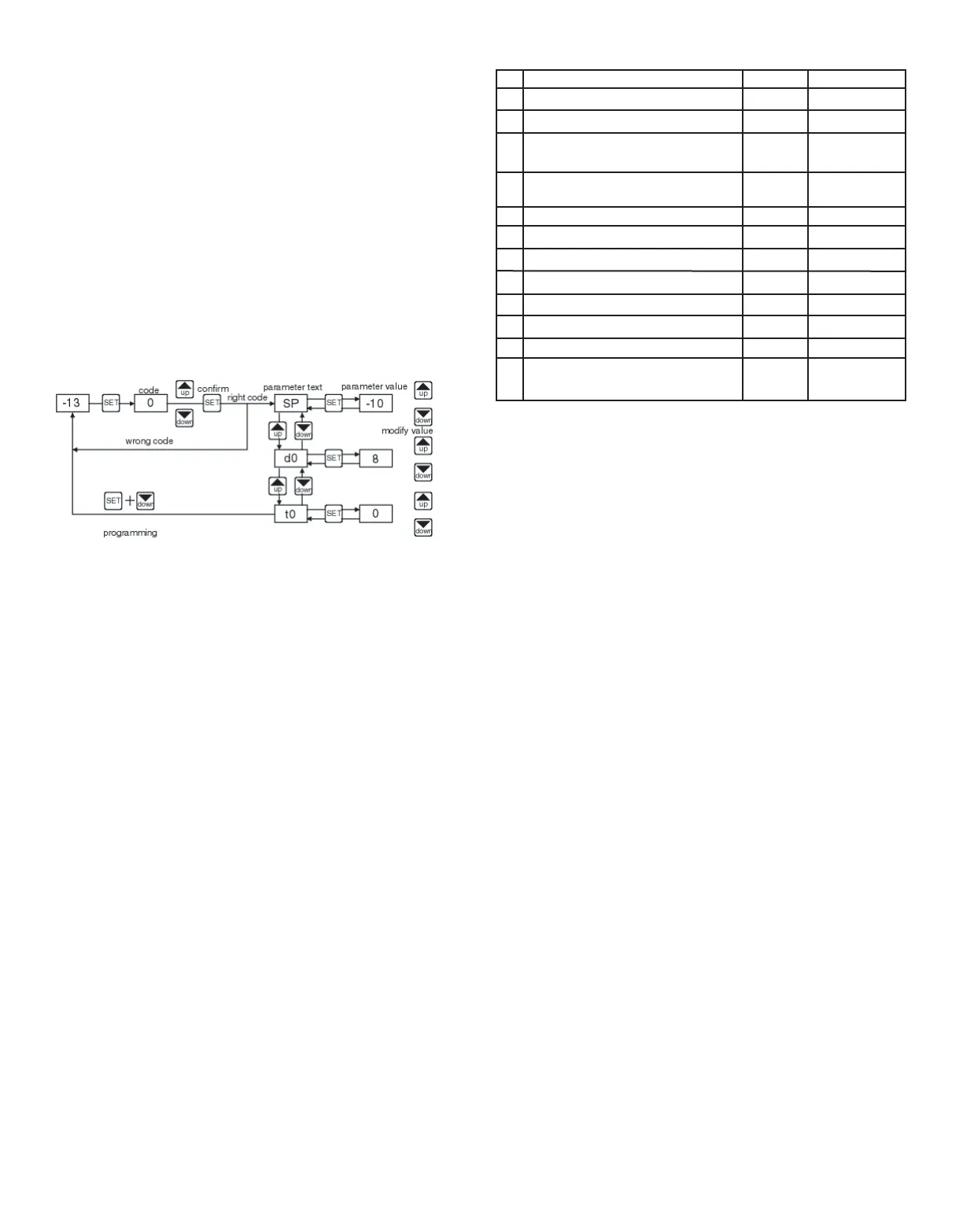
Access to all parameters (code protected):
•Press SET for 8 seconds. The access code value 00 is shown on
the display.
•Using the UP and DOWN buttons, set the code (factory-set code
is 00).
•Press SET to enter the code. If it is correct, the first parameter
label will be shown on the display (SP).
•Move to the desired parameter with the UP and DOWN keys.
•Press SET to see the value.
•Modify the value with the UP and DOWN keys.
•Press SET to enter it, and exit to text parameter.
•Press SET and DOWN to quit programming, or wait 1 minute for
the TIMEOUT.
SETTING THE KEYBOARD CODE TO ZERO
The keyboard code can be set to zero by holding the SET key and
turning the controller off then on again.
LED INDICATIONS
Out: This indicates that the compressor is connected. It waits the
programmed minimum stop time of the compressor.
Def: This indicates that defrosting is activated.
MESSAGES DISPLAY
In normal operation, the probe temperature will be shown. In case
of alarm or error, the following messages will be shown:
• Er- Memory error.
• -- Short-circuited probe error.
• oo- Open probe error.
PPAARRAAMMEETTEERRSS
PPAARRAAMMEETTEERR DDEESSCCRRIIPPTTIIOONNSS
SSPP == SSeett PPooiinntt..
Temperature wished to regulate the machine. Can
vary from r1 to r2.
rr00 == DDiiffffeerreennttiiaall..
Heating: If temperature is ≥ Set then out OFF. If
temperature is ≤ Set then out OFF. Cooling: if temperature is > Set
+ r0 then out ON. If temperature is ≤ Set then out OFF.
rr11 == LLoowweer
r SSeett PPooiinntt LLiimmiitt
rr22 == HHiigghheerr SSeett PPooiinntt LLiimmiitt
dd00 == HHeeaatt oorr CCoooolliinngg CCoonnttrrooll..
Ht = heating control, Co = cooling
control.
dd22 == DDeeffrroossttiinngg TTiimmee RRe
emmaaiinniinngg
, in minutes. If d2 = 0, defrosting
will not start.
dd88 == IInntteerrvvaall BBeettwweeeenn TTwwoo DDeeffrroossttiinnggss
, in hours.
cc00 == MMiinniimmuumm ttiimmee ffoorr ccoommpprreessssoorr ttoo bbee OOFFFF..
Minimum time from
when the compressor stops till it connects again.
cc11 ==
CCoonnttiinnuuoouuss CCyyccllee TTiimmee..
The remaining time for a continuous
cold cycle.
PP11 == AAmmbbiieenntt PPrroobbee CCaalliibbrraattiioonn..
Offsets degrees to adjust the
ambient probe.
HH55 == AAcccceessss CCooddee ttoo PPaarraammeetteerrss..
Factory-set as 00.
tt00 == T
Teemmppeerraattuurree DDiissppllaayy LLiimmiitt..
Maximum temperature shown on
the display, although the real temperature can be greater.
OPERATION IN CASE OF ERROR
If the probe or thermostat memory should fail, the compressor will
be connected for 5 minutes ON then 5 minutes OFF.
MAINTENANCE
CLEANING
Clean the surface of the display controller with a soft, damp cloth.
Never use abrasive detergents, petrol, alcohol or solvents.
REPAIRS
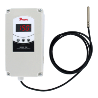
A
fter final installation of the TS Series Digital Temperature Switch, no routine
maintenance is required. A periodic check of system calibration is recom-
mended. The devices are not field repairable and should be returned to the
factory if recalibration or other service is required. After first obtaining a
Returned Goods Authorization (RGA) number, send the material, freight pre-
paid, to the following address. Please include a clear
description of the problem plus any application information
available.
Dwyer Instruments
Attn: Repair Department
102 Highway 212
Michigan City, IN 46360 U.S.A
SP
r0
r1
r2
d0
d2
d8
c0
c1
P1
H5
t0
Description
Set point
Differential or hysteresis
Lower value for set point
Higher value for set point
Heating or cooling control
Time for defrosting
Interval time between defrosting
Minimum stop time for compressor
Continuous cycle time
Ambient probe adjustment
Parameter access code
Maximum temperature on display
Units
degrees
degrees
degrees
degrees
option
minutes
hours
minutes
hours
degrees
numeric
degrees
Range
r1 to r2
1 to 20°
-50 to 150°C
-50 to 302°F
-50 to 150°C
-50 to 302°F
Ht/Co
0 to 59’
0 to 24
0 to 59’
0 to 24
-10° to 10°
0 to 99
-50 to 150°C
-50 to 302°F
exits
T-TS2 12/8/06 10:03 AM Page 2
 Loading...