Dyer Environmental Controls Ltd
L AZN- AE B
RM
K-T
RT
ZA S
RT 45
Breakglass
2 8 3 1 6 4 7
10kΩ
3 2
LT MOT
SD-O 371
Smoke detector
LT 84-U
Wall Switch
10kΩ
5
COM
10kΩ
1k Ω
Fire alarm
interface
Normally
open, volt
free contact.
-R
OR
10kΩ resistor - orange band
(from RM “R” & “-” in panel).
1kΩ resistor -
red band (from
keyring bag).
10kΩ resistor - orange band
(from RT “T” & “-” in panel).
EM 47 K
Orange
Black
Black
Vent
24v D+H
Mechatronic
drive.
Orange
(High Speed)
White
Brown
Terminal resistor end of line module
(from MOT E, A & B in panel).
Connection point
(local to vent - by
others)
Terminate all
other coloured
cables in
connection
point.
Breakglass display indications
+ +
Solid green - System healthy, no faults.
+ +
Solid green, ashing yellow - System healthy, no fault.
Inbuilt service timer expired. Contact Dyer’s service &
maintenance department.
+ +
Flashing yellow - System fault. See panel display
indications below.
+ +
Solid red - System in re.
Line
Group
D79D47 D42 D20
D14
Panel display indications
D47
Line
• Indicates an issue between the control panel and
control elements (re alarm interface, smoke detector
or breakglass, line button in ‘off’ position).
• Each control element requires a single 10kΩ end of line
resistor. See above detail.
• If no re alarm interface or smoke detector in system,
leave 10kΩ end of line resistor in RM terminals “R” & “-”.
• Check external signal fuse has not blown.
• Ensure line button at top of panel is in ‘on’ position at
all times.
D42
Alarm
• System in re.
D20
Control
• System healthy, no faults.
D79
Group
• Issue between the control panel and the drive(s).
Ensure EM 47 K drive group end of line is connected as
indicated above.
• Check 1.6 Amp (4402) / 3.15 Amp (4404) fuse has not
blown.
D14
Battery
• Incorrect connection of the batteries or 3.15 Amp fuse
blown.
Alarm open Reset close
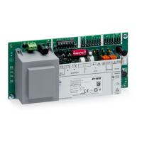
RZN 4402/04-K V2 Troubleshooting Guide
Dyer Environmental Controls Ltd, Unit 10, Lawnhurst Trading Estate, Cheadle Heath, Stockport, Cheshire SK3 0SD Page 1 of 2
www.dyerenvironmental.co.uk +44 (0)161 491 4840 Registered in England 02670985 VAT No. 611329279 V1