4.8 4.8 System Board 4 Replacement
Procedures
Satellite C40-G/Pro-C40-G Maintenance Manual 4-20
4.8 System Board
Removing System Board
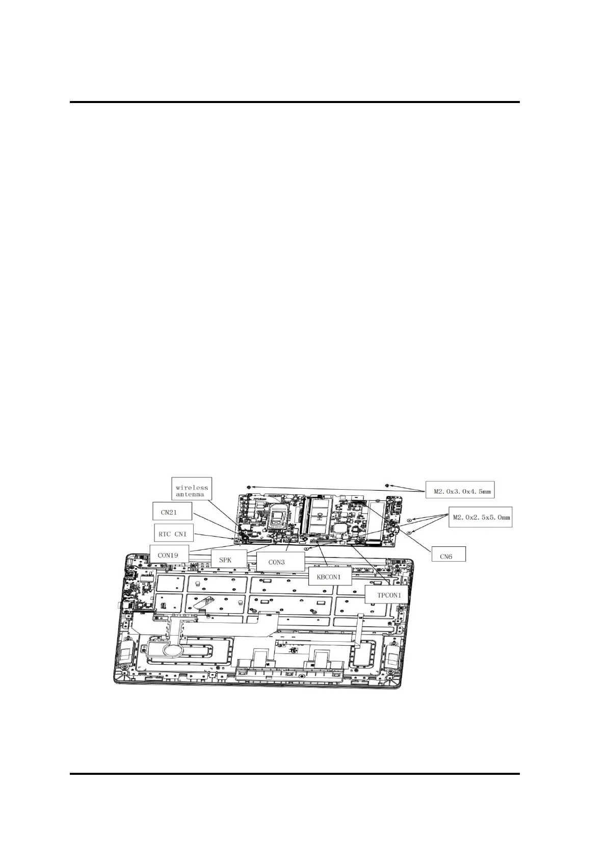
Remove System Board according to the following procedures and Figures 4-21.
1. Disconnect the following cable from the connector on System Board:
- Speaker cable from SPK.
- LCD cable from CN6.
- IO Board cable from CON19
- Touch Pad cable from TPCON1.
- Keyboard cable from KBCON1.
- FAN cable from CN21.
- Battery Pack cable from CN3.
- RTC Battery from RTCCN1.
- Released wireless antenna cables from top cover latch.
2. Remove two M2.0x3.0x4.5and three M2.0x2.5x5.0 black Phillips head screw
securing System Board.
3. Remove System Board.
4. Remove the high position adhesive paper of DC seat
 Loading...