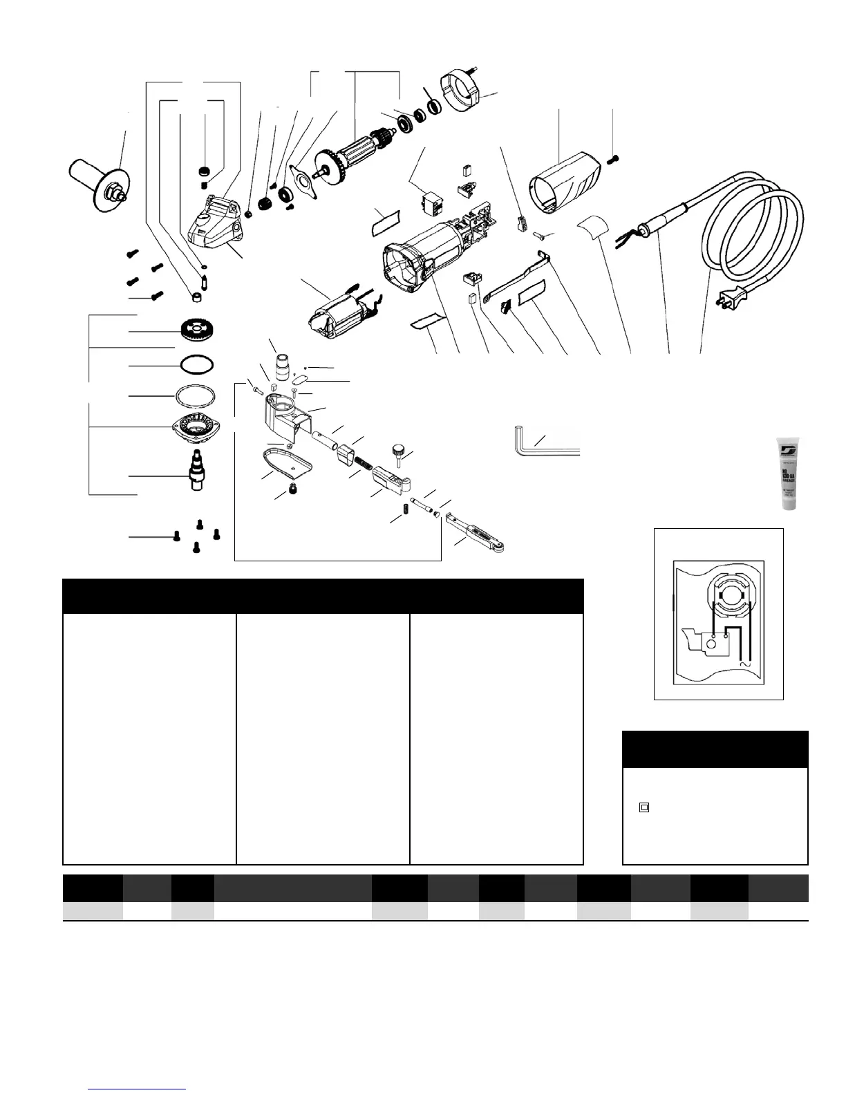
Model 40610 Complete Assembly
3
1 11203 Contact Arm Assembly
2 40759 Belt Housing Assembly
2.1 96334 Plug
2.2 15308 Guide Post
2.3 11040 Spring
2.4 15306 Tension Arm
2.5 95426 Spring
2.6 15309 Shield
2.7 15307 Tension Shaft
2.8 15329 Captive Screw
2.9 15312 Housing Cover
(Includes 15329)
2.10 96335 Hex Nut
2.11 40760 Belt Housing
(Includes 40761, 95442)
2.11.1 95442 Screw
2.11.2 40761 Label - Belt Housing
2.12 95311 Screw
2.13 40029 Cam Lock
2.14 95217 Screw
3 95218 Knob
4 15336 Drive Wheel
5 40724 Screw (4)
6 40762 Spindle Assembly
6.1 40763 Spindle
6.2 40728 Washer
6.3 40729 O-Ring
6.4 40730 Pinion/Gear Set
7 40731 Screw (6)
8 40258 Side Handle
9 40733 Gear Housing Assy.
9.1 40734 Spindle Lock Assy.
10 40735 Nut
11 40736 Screw (2)
12 40737 Armature Assembly
12.1 02649 Bearing
12.2 40738 Bearing Retainer
12.3 40739 Bearing Shield
12.4 01015 Bearing
13 40740 Bearing Seat
14 40741 Fan Baffle
15 40742 Field Coil Assembly
16 40764 Label - Specification
17 40744 Switch
18 40746 Cord Clamp
19 40747 Rear Cover
20 40748 Label - Safety
21 40749 Motor Housing
22 40750 Carbon Brush Set
23 40751 Brush Holder
24 40752 Switch Button
25 40753 Label - Logo
26 40754 Switch Rod
27 40755 Label - Maintenance
28 40756 Cord Sleeve
29 40757 Cord Set
30 95134 Hex Wrench (9/64")
Index Key
No. Part # Description
Wiring Diagram
One Year Warranty
Following the reasonable assumption that any inherent defect which might prevail in a product will become apparent to the user within one year from the date of
purchase, all equipment of our manufacture is warranted against defects in workmanship and materials under normal use and service. We shall repair or replace at
our factory, any equipment or part thereof which shall, within one year after delivery to the original purchaser, indicate upon our examination to have been defective.
Our obligation is contingent upon proper use of Dynabrade tools in accordance with factory recommendations, instructions and safety practices. It shall not apply to
equipment which has been subject to misuse, negligence, accident or tampering in any way so as to affect its normal performance. Normally wearable parts such as
bearings, brushes, gears, etc., are not covered under this warranty.
2.3
1
2.1
2.2
3
2.6
2.7
2.14
2.11
2.10
2.11.2
2.11.1
2.13
2.12
5
6.1
6.3
6.2
6.4
6
8
9.1
9
6.4
11
12.1
12.2
12.3
12.4
13
12
16
17
19
14
18
7
29282726252423222120
15
Grease
7
7
2.9
10
95542 Grease 10 oz.
•
High film strength; excellent
resistance to water, steam, etc.
•
Workable range 0˚ F to 300˚ F.
Model Motor Abrasive Belt Size Max. SFPM Weight Length Height
Number RPM Watts Inch (mm) Voltage Current Phase Frequency (SMPM) Pound (kg) Inch (mm) Inch (mm)
All Models 11,000 680 1/4-3/4 (6-19) W x 18-24 (457-610) L 120 V (AC) 6 amp. 1 60 Hz 2,520 (768) 5 (2.3) 19 (483) 5.5 (140)
30
4
2.8
2.5
2.4
A . . . . . . . . . . . . . . . . . . . . .amperes
Hz . . . . . . . . . . . . . . . . . . . . . . . .hertz
. . . . . . . . . .Class II Construction
RPM . . . . . . . . .revolutions per minute
v . . . . . . . . . . . . . . . . . . . . . . . .volts
w . . . . . . . . . . . . . . . . . . . . . . . .watts
Definitions of Label Symbols
Symbol Description
2
 Loading...