Disassembly, Assembly Instructions - 2.8 hp Grinder/Sander Series:
Ø 7" & 9", Right Angle
Models: Use for all models.
Important: Disconnect from the air supply.
Notice: Use these instructions along with the specific tool manual for each model.
To avoid damage, use the proper repair tools designed for motor disassembly and
assembly.
! Remove any flanges, abrasive, back-up disc or guard.
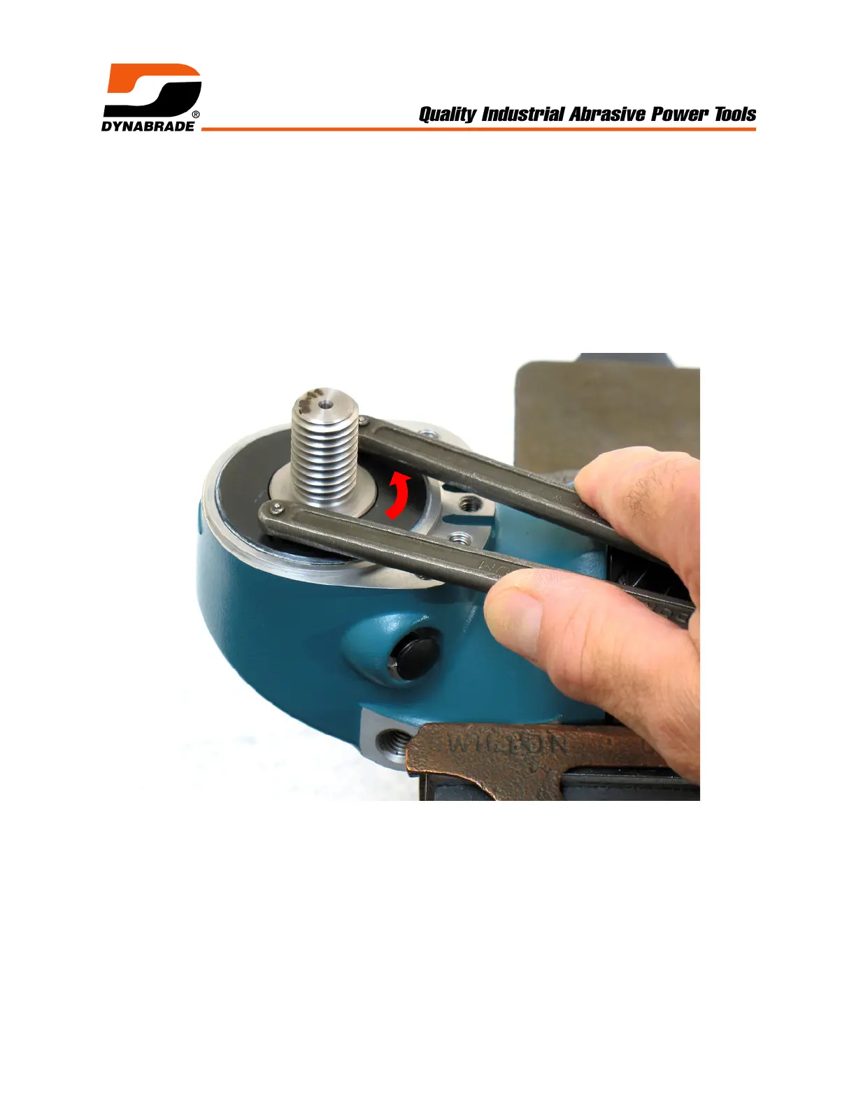
Gear Disassembly: (Tutorial shows tool with 54951 Spindle. - Applies to all models.)
1. Use an adjustable pin spanner (Ø 4mm pins) to remove 54952 Lock Ring.
! Turn counterclockwise.
 Loading...