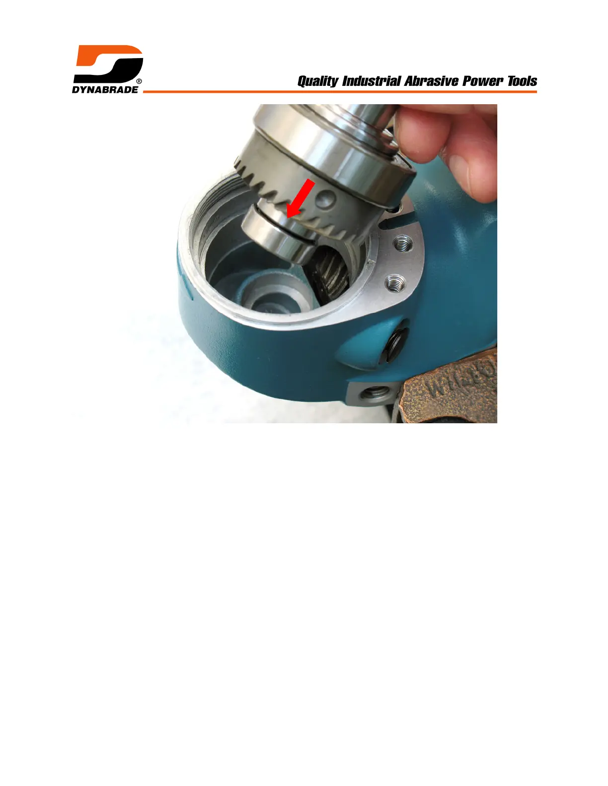
4. Fasten housing in vise (bronze or aluminum jaws). Install spindle assembly in
housing.
! By hand, push down on spindle assembly and rotate spindle back and forth to
check the amount of free movement (“backlash”) between the bevel and pinion
gear teeth. Ideally, there should be minimal free movement between the teeth.
! Use an adjustable pin spanner (Ø 4mm pins) to fasten 54952 Lock Ring. Check
360° rotation of the spindle assembly. The correct fit should have minimal
“backlash” without any restricted movement between the gears.
! When gear fit is too tight, add shim(s) to adjust and set the correct “backlash”.
! Notice: Once gears are adjusted correctly. Loosen 54952 Lock Ring and remove
spindle assembly from housing.