8
I. Power Supply (Control Box)
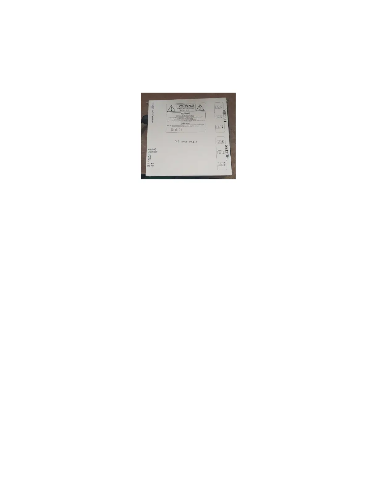
The POWER SUPPLY is the control center of the sauna room. It is installed on the
topside of the ROOF PANEL and has inputs/outputs connected to it. (see Figure 1)
Figure 1
POWER IN - main power of the sauna room
HT1, HT2, HT3, HT4, HT5, HT6 – heat emitter cords
LAMPROOF – roof lamp power (optional)
LIGHTING – chromotherapy lights
PANEL CONTROL – control panel
FUSE RESET – protects against power
II. Component Labeling
Power Cord – Main power cord connects the POWER SUPPLY to the
dedicated wall outlet
HT1, HT2, HT3, HT4, HT5, HT6 – Heater cords connect the heat emitters
to the POWER SUPPLY at these ports (HT5 & HT6 are not used on most
models)
Lighting – Connects the interior lighting to the POWER SUPPLY at this
port
LampRoof – Connects the exterior roof lights to the POWER SUPPLY at
this port
Panel Control – Connects the Control Panel through the CTRL harness
to the Power Supply at this port
L/R Speakers – Connects the speakers through these wires to the Control
Panel
Temp Sensor – Connects the Temperature Sensor through this wire to
the Control Panel