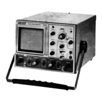
The B&K-Precision Model 1476 is a 10 MHz, triggered sweep, dual-trace oscilloscope designed for professional use in observing and measuring waveforms in electronic circuits. It offers dual vertical inputs for simultaneous viewing of two waveforms, with low-frequency, low-repetition-rate waveforms chopped at 200 kHz, and high-speed, high-repetition-rate waveforms viewed using alternate sweep. Its features make it suitable for troubleshooting, electronic equipment repair, research, development, and laboratory instruction.
Function Description:
The oscilloscope allows for single-trace or dual-trace operation, displaying input waveforms either individually or simultaneously. It incorporates a triggered sweep system for stable waveform presentations, ensuring synchronization with the observed signal. The unit can also function as a vectorscope for color display analysis, as specified by color television manufacturers. An external horizontal input (X-Y operation) is available for specific measurements, such as phase measurement or external sweep voltage. Intensity modulation (Z-axis input) is provided for time or frequency markers, compatible with TTL logic.
Important Technical Specifications:
- Vertical Amplifiers (CH A and CH B):
- Deflection Factor: 0.01 V/cm to 20 V/cm in 11 calibrated ranges (1-2-5 sequence), with variable adjustment between ranges.
- Calibration Accuracy: ±5% on all ranges.
- Frequency Response: DC to 10 MHz (-3 dB) for DC coupling; 2 Hz to 10 MHz (-3 dB) for AC coupling.
- Risetime: 35 nanoseconds.
- Overshoot: 3% or less at 100 kHz squarewave display.
- Ringing: 3% or less at 100 kHz squarewave display.
- Input Resistance: 1 megohm, ±5%.
- Input Capacity: 22 pF (±3 pF).
- Max. Input Voltage: 300 V (DC + AC peak) or 600 V p-p.
- Operating Modes: Channel A only, Channel B only, Dual-trace (chopped at 200 kHz for 1 mS/cm and slower sweeps; alternate trace for faster sweeps).
- Channel Separation: Better than 60 dB @ 1 kHz.
- Sweep Circuits (Common to CH A and CH B):
- Sweep System: Triggered and automatic. Automatic mode provides sweep without input signal.
- Sweep Time: 1 µSEC/cm to 0.5 SEC/cm in 18 calibrated ranges (1-2-5 sequence), with variable adjustment between ranges.
- Sweep Time Accuracy: ±5%.
- Sweep Magnification: 5 times from center, maximum sweep speed 0.2 µSEC/cm.
- Horizontal Linearity: 3% or less distortion.
- Triggering:
- Source: INT (CH A or CH B signal) and EXT (external signal via EXT TRIG jack).
- Slope: Positive and negative, continuously variable level control; pull for AUTO.
- Triggering Range: INT: 20 Hz to 10 MHz (min. 1 cm deflection); EXT: DC to 10 MHz.
- Video Sync: Vertical and horizontal sync separator for composite video waveforms. FRAME sync (0.5 SEC/cm to 0.1 mSEC/cm) and LINE sync (50 µSEC/cm to 1 µSEC/cm) automatically switched.
- Horizontal Amplifier (Horizontal Input through CH B Input):
- Deflection Factor: 0.01 V/cm to 20 V/cm.
- Frequency Response: DC to 1 MHz (-3 dB).
- Input Resistance: 1 megohm (nominal).
- Input Capacity: 22 pF (±3 pF).
- Maximum Input Voltage: 300 V (DC + AC peak) or 600 V p-p.
- X-Y Operation: CH A input for Y (vertical), CH B input for X (horizontal).
- Calibration Voltage: 1 V p-p square wave (±5%) at line frequency.
- Intensity Modulation (Z-Axis Input): TTL logic-compatible, high logic increases brightness, low logic decreases brightness. Input Resistance: 10 kΩ (nominal).
- Power Requirements: 120 or 240 V AC, ±10%, 50/60 Hz, 20 watts. (3-wire line cord, CSA-approved).
- Probes: PR-31, PR-35, PR-36, PR-37 (combination 10:1 and direct). 10:1: 10 megohms, 18 pF; Direct: 1 megohm, 120 pF. BNC connector with spring-loaded, hook-on tip.
- Screen: 130 mm (approx. 5.1 inches) diameter CRT with an 8 x 10 cm rectangular viewing area.
Usage Features:
- Initial Starting Procedure: Includes setting power switch to OFF, connecting to AC outlet, centering position controls, pulling TRIGGERING LEVEL to AUTO, setting DC-GND-AC switches to GND, setting MODE to CH A or DUAL, turning on power, waiting for CRT warm-up, adjusting INTENSITY and FOCUS for a sharp trace, and centering traces.
- Single-Trace Waveform Observation: Connect probe to CH A INPUT, set probe to 10:1 attenuation (or DIRect for low amplitudes), set DC-GND-AC to AC (or DC for very low frequencies/DC measurements, GND for zero-signal reference), connect ground clip to chassis ground, connect probe tip to measurement point, set VOLTS/CM for 2-6 cm vertical deflection, set SOURCE to INT (or EXT for external sync), set SYNC to SLOPE (+/-) or VIDEO (+/-), adjust TRIGGERING LEVEL for synchronized display, set SWEEP TIME/CM for desired waveforms, and use PULL 5X MAG for expanded view.
- Calibrated Voltage Measurement: Display waveform, set VOLTS/CM for maximum vertical deflection, read vertical deflection in cm, calculate voltage (vertical deflection x VOLTS/CM setting x probe attenuation).
- Calibrated Time Measurement: Display waveform, set SWEEP TIME/CM for largest possible display of waveform segment, readjust TRIGGERING LEVEL if needed, read horizontal deflection in cm, calculate time duration (horizontal deflection x SWEEP TIME/CM setting).
- External Horizontal Input (X-Y Operation): Set SWEEP TIME/CM to CH B position, use CH A for Y input and CH B for X input, adjust CH B VOLTS/CM for horizontal deflection. Sync controls are disconnected.
- Z-Axis Input: Apply TTL-compatible signal to INT MOD jack for intensity modulation.
- Dual-Trace Waveform Observation: Connect probes to CH A and CH B INPUT jacks, set probes to 10:1 (or DIRect), set MODE to DUAL, adjust CH A and CH B POSITION controls, set DC-GND-AC switches to AC, connect ground clips, connect probe tips, set VOLTS/CM controls for 2-3 cm vertical deflection, set SOURCE to INT (or EXT), set SYNC to SLOPE (+/-) or VIDEO (+/-), adjust TRIGGERING LEVEL for synchronized sweep, set SWEEP TIME/CM for desired waveforms, and use PULL 5X MAG for expanded view.
- Dual-Trace Applications: Useful for frequency divider waveforms, digital circuit time relationships, gated ringing circuits, delay line tests, stereo amplifier servicing, and video equipment servicing (e.g., VITS analysis).
- Television Alignment: Supports tuner, IF, and chroma alignment using sweep-frequency techniques with a sweep/marker generator. Procedures involve connecting sweep generator to antenna terminals or mixer input, synchronizing oscilloscope sweep, connecting vertical probe to test points (e.g., video detector output), and observing response curves.
- FM Receiver Alignment: Involves connecting a sweep generator to the mixer input, connecting sweep voltage output to CH B input, connecting vertical input probe to demodulator input, adjusting gain controls, setting marker generator to 10.7 MHz, and aligning IF amplifiers.
- Phase Measurement: Uses X-Y operation with a sine wave input to both vertical and horizontal inputs to display Lissajous patterns, from which phase difference can be calculated.
- Frequency Measurement: Uses X-Y operation with a known frequency sine wave to one input and an unknown frequency sine wave to the other, displaying Lissajous patterns to determine frequency ratio.
- Square Wave Testing of Amplifiers: Connects a square wave generator to the amplifier input and the oscilloscope probe to the amplifier output to observe distortion characteristics.
Maintenance Features:
- Calibration Source: A built-in 1 V p-p square wave allows for checking and recalibration of vertical amplifiers.
- Housing Removal: Involves removing 6 screws (2 left, 2 right, 2 top) and lifting the cover.
- 240 VAC Operation: Requires removing the housing, rotating a plug (P101) 180 degrees, and replacing a 0.7A fuse with a 0.3A fuse.
- CRT Rotation Adjustment: Loosen two screws on the rear panel, rotate the cover to align the horizontal trace with the graticule line, and tighten screws.
- DC Balance Adjustment: Adjust CH A or CH B DC BAL (side panel screwdriver adjustment) to minimize vertical trace movement when rotating the VOLTS/CM switch.
- Vertical Gain Adjustment: Apply a 1 kHz, 50mV p-p square wave to CH A input, set MODE to CH A, and adjust VR103 (CHA GAIN ADJ) for 5 cm deflection. Repeat for CH B using VR113 (CHB GAIN ADJ).
- Horizontal Position Adjustment: Center the POSITION control, set SWEEP TIME/CM to 1mS/CM, adjust VR305 (POS ADJ) for horizontal centering, and check deflection range.
- Astigmatism Adjustment: Set SWEEP TIME/CM to EXT H., adjust FOCUS control and VR106 (ASTIG) for a small, bright spot.
- Probe Compensation Adjustment: Adjust probe compensation for best square wave display while observing the signal from the CAL 1V p-p terminal.
Safety Precautions:
The manual includes a WARNING section emphasizing electrical shock hazards. Users are advised to avoid exposing high voltage unnecessarily, use insulated surfaces, employ the "one hand in the pocket" technique, use an isolation transformer for "hot chassis" equipment, use 3-wire outlets for 3-wire power plugs, familiarize themselves with high voltage points, be aware of AC line voltage presence even when off, and never work alone. Training in CPR is highly recommended. High voltage (up to 2000V) is present on the CRT and vertical amplifier & power supply board when operating, and up to 180V DC on the sweep board. Line voltage (120/240 VAC) is present on the power transformer and on-off switch even when the unit is off.