ILER-20 MK2 SSB QRP Transceiver Kit Page 15
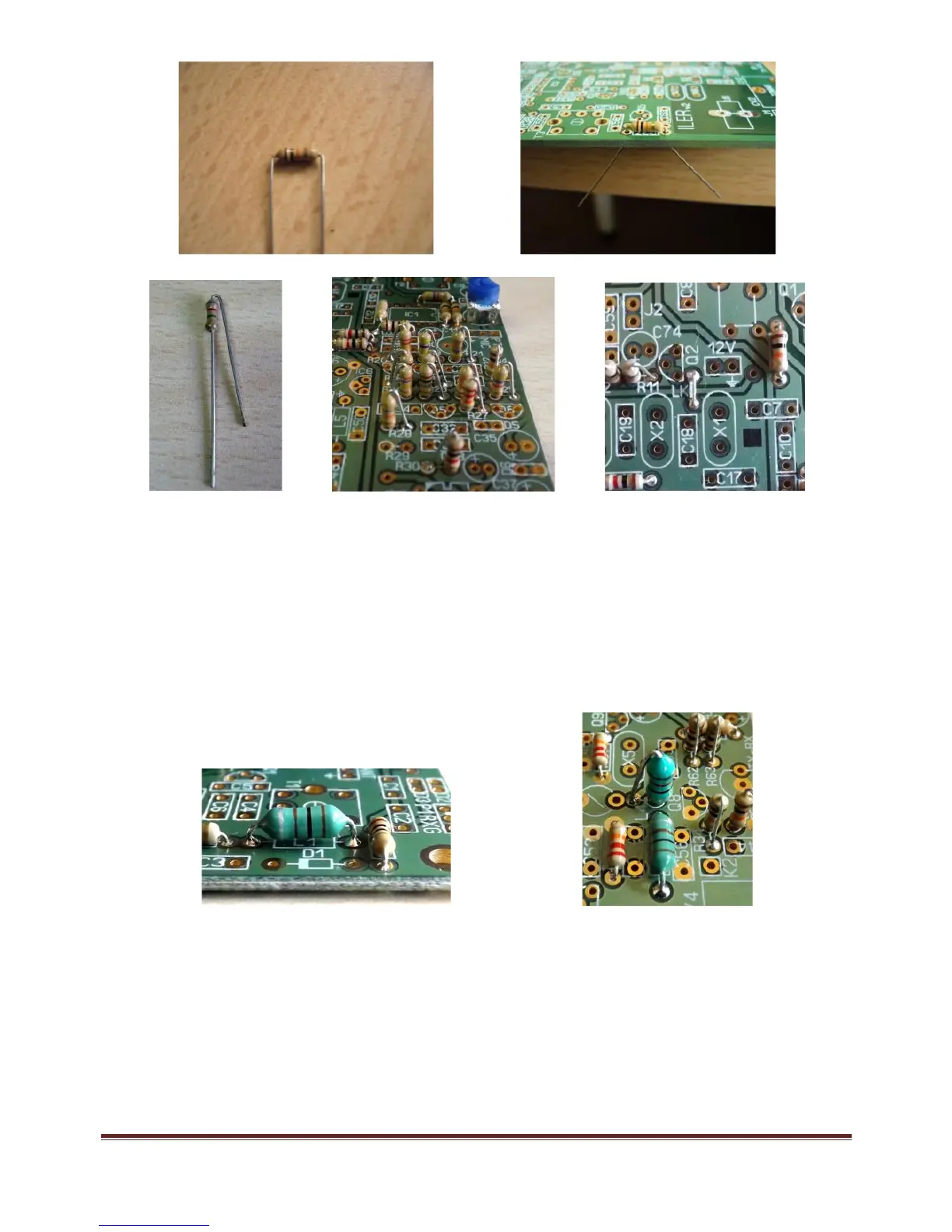
Axial Inductors
L1, L2, L3, L4 L5, L7, L9
These components look like thick-bodied resistors and the body is colored blue or green. In its interior
there is a small coil wound on a ferrite core. Refer to the parts list to select the correct component for
each location. Mount the inductors in their respective locations, as identified on the circuit board, in t he
same manner as you did with the resistors, but leave a separation of 1-1.5mm from t he board.
Note: L4 is mounted vertically.
Diodes
Next mount the diodes, being careful to place them with the correct orientation. There is a band on one
end of each diode that corresponds to the component outline on the circuit board.
D1, D2, D3, D4 and D5 are 1N4148; they are normally orange in color with a black band and they have
the type “4148” printed on t he body. Note that some diodes are mounted in a vertical position.
D8 is similar to the 1N4148 but slightly t hicker. It is marked as BZX85C47.
D6 and D7 are 1N4007 diodes; they are black with a gray band. Mount D6 only.
DO NOT MOUNT diode D7 now (“bias” limiter), nor the bi-color LED rx/tx D9.
 Loading...