EA4TX – ARS-USB Manual – June. 2024 Page 12
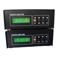
The following illustration shows the correct Rotator + Control Unit + ARS-USB wiring:
You can find the two wires by looking at the circuit diagram included with the rotator.
Be very careful with the polarity! J4-4 is the negative input or reference
connection and J4-5 is the cursor of the potentiometer. It is important that you check
the actual voltage at these points with a voltmeter. This can be achieved by turning
the antenna from one end to the other and writing down all the voltage readings at
both ends. You should also observe that the voltage increases or decreases between
its ends while the rotator and antenna are turning. Remember that one end will
correspond to 0V and the other to the maximum voltage “V”.
Note: If you Potentiometer rotor is grounded it’s highly recommended to connect
the V- input (J4-4) to the ARS-USB ground (J4-3).
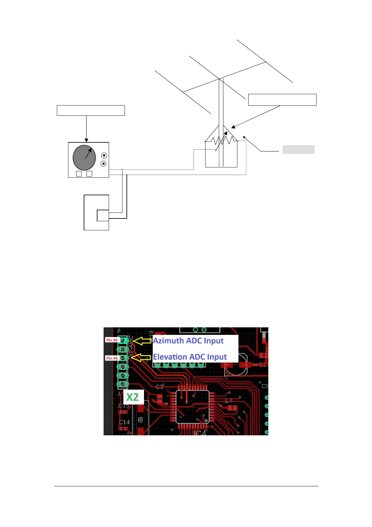
Azimuth Calibration:
Move the Azimuth rotor to the CW limit (right limit). Check the voltage at X2 pin #6.
The X2-ADC pin #6 is the Azimuth ADC Input @ microprocessor. Adjust Pot1 until
you obtain a reading of 5.0V. When Pot1 is moved CW, the signal input will be
amplified. When it’s moved CCW, it will be attenuated.
ARS-USB
J4
N
S
Potentiometer 500Oh
Control Unit
ROTATOR
 Loading...