EA4TX – ARS-USB Manual – June. 2024 Page 13
Elevation Calibration:
Similar to the azimuth calibration, elevation calibration is accomplished by a similar
process at X2 pin #4.
Note: Instead of using a voltmeter connected at X2 pin #6 and pin #4, you can use
the calibration function in the software for making the Pot1 or Pot2 adjustments. In
this case, you will use the ADC indicator (0 to 1023)
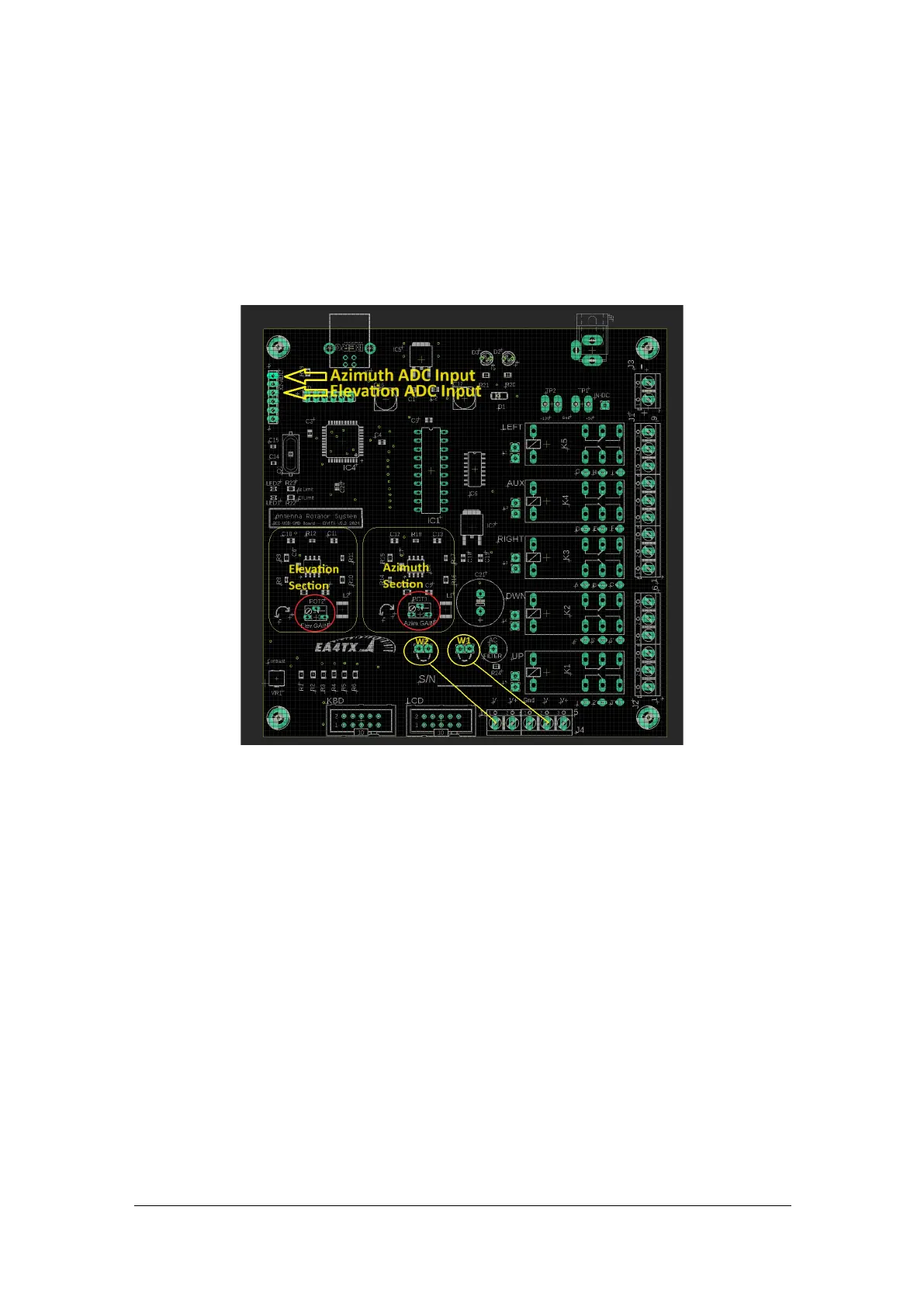
1.6.1 PCB Description
J4 is the Voltage feedback Input. In most cases, this Input is referenced to ground, so
“V-“ should be connected to GND.
From left to right the inputs are:
J4-1: Elevation V-
J4-2: Elevation V+
J4-3: Ground Reference
J4-4: Azimuth V-
J4-5: Azimuth V+
Note: Most rotors are referenced to ground, so J4-1 (V-) and J4-4 (V-) must be wired
to J4-3.
Note: There are 2 points marked as W1 (Azimuth) and W2 (Elevation) where you
can easily make a bridge to connect V- to Ground.
 Loading...