EA4TX – ARS-USB Manual – June. 2024 Page 4
Part 1
ARS-USB circuit Setup
The ARS-USB circuit fulfils the two following objectives:
It reads the current antenna position by means of an incorporated A/D
converter.
It controls the movement of the rotor. For an azimuth rotor, this would be
right or CW and left or CCW. This is accomplished through relays using the data
obtained from the A/D converter.
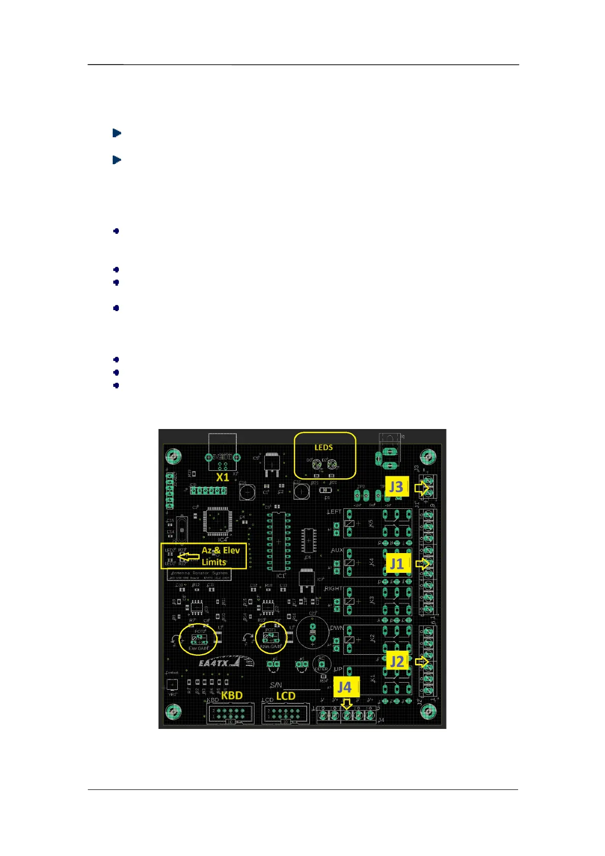
The ARS-USB has the following connectors:
J1: The azimuth antenna rotation is controlled by means of this connector. It
is attached to 3 relays on the ARS-USB Board. One of the relays provided (AUX)
is able to control a brake.
J2: Similar than J1, J2 is used for elevation control.
J3: Power input. Connection point for the required 12 - 14 Vdc regulated
power supply. Correct polarity is required.
J4: Input to the A/D converters for the azimuth & elevation rotators. This input
is used to read the antenna position. This point will be connected in parallel with
the wires attached to the rotor’s potentiometer enabling the readout of the
antenna position.
X1: USB Port.
LCD: IDC connector used to attach the LCD.
KBD: IDC connector used by the Keyboard.
The following image is the ARS-USB circuit schematic allowing easy location of the
different connectors:
 Loading...