EA4TX – ARS-USB Manual – June. 2024 Page 5
1.1 Connector J1: Azimuth Relay connections
The ARS-USB has two relays to control the Azimuth movement: right (CW) or left
(CCW). An additional relay (AUX), located between them may be used to control a
brake in rotators requiring a braking function.
These relays are 2 position with 2 circuit switches. Each circuit supports 5A at 220V.
One of the two circuits of each relay is already wired and attached to its connector as
it appears in the following image.
In this manual, the 9 terminals of this connector will be called
J1-1, J1-2, J1-3, J1-4, J1-5, J1-6, J1-7, J1-8 and J1-9.
In de-energised position, J1-2 is switched to J1-1. When it’s activated, J1-2 is
switched to J1-3.
In de-energised position, J1-5 is switched to J1-4. When it’s activated, J1-5 is
switched to J1-6.
In de-energised position, J1-8 is switched to J1-7. When it’s activated, J1-8 is
switched to J1-9.
Relay OFF Relay ON
Right/CW J1-2 to J1-1 J1-2 to J1-3
AUX J1-5 to J1-4 J1-5 to J1-6
Left/CCW J1-8 to J1-7 J1-8 to J1-9
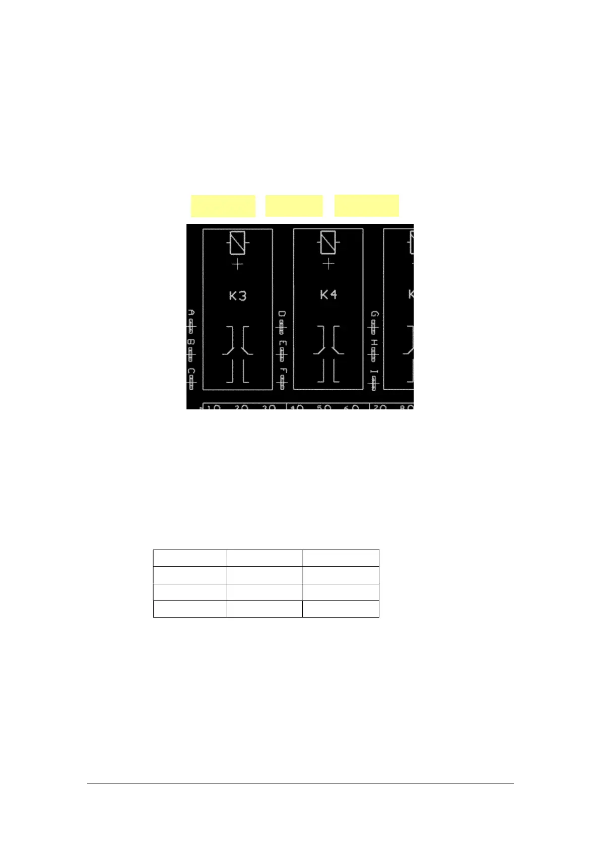
This first circuit (available at J1) will be used to control movement to the right or left. If
necessary, the second circuit can be used to make a second electric circuit active on
the rotor. It is silk-screen printed on the circuit board. It is next to the relays and
identified with the following references:
A B C D E F G H I
RIGHT relay
AUX relay
LEFT relay
 Loading...