Do you have a question about the Eagle Signal B506 and is the answer not in the manual?
Lists key features such as 17 programmable modes, batch count, dual setpoints, 1ms resolution, security levels, LED display, IP65 rating, and inhibit input.
Explains DIN rail or panel mounting using a bracket, emphasizing a snug fit without overtightening screws.
Provides wiring diagrams for B506-2001/2 and B506-2051/2 models, detailing connections for inputs, outputs, and power.
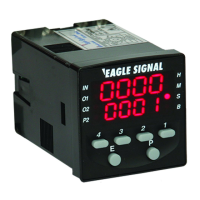
Details front panel controls and indicators such as Primary Display, Time Range, I/O Status, Batch Indicator, Preset 2 Indicator, Set Value, Numeric Keys, Program Key, and Edit Key.
Explains how to view and modify Preset 1, Preset 2, and Batch displays and values using the front panel keys.
Describes how to enter Program Mode and navigate parameters like Operating Function, Output 2 Operation, and Preset 2 Operation.
Sets the duration of Output 2, within a range from 1 second to 9999 seconds.
Sets the unit of measure for time values used for Preset 1 (Seconds, Minutes, Hours, etc.).
Determines the resolution of the selected time range for Preset 1, settable from 0000 to 0.000.
Sets the unit of measure for time values used for Preset 2 (Seconds, Minutes, Hours, etc.).
Determines the resolution of the selected time range for Preset 2, settable from 0000 to 0.000.
Determines if time values increment from zero or decrement from the set value to change output state.
Configures if the unit resets upon power reapplication or continues from the interruption point.
Enables or disables reset functionality via simultaneous key presses on the front panel.
Defines four levels of security for access to program mode and setpoint changes.
Illustrates timing diagrams for various operating functions like On Delay, showing activation and deactivation conditions.
Provides a flowchart illustrating the programming sequence and parameter dependencies for configuring the timer.
Lists technical specifications including inputs, outputs, physical dimensions, operating voltage, power consumption, time ranges, resolution, accuracy, and environmental ratings.
Provides a list of available timer models, their descriptions, and corresponding model numbers for timers and accessories.
A blank section designated for user notes.
Outlines the standard two-year warranty terms, repair/replacement policy, limitations, and exclusion of other warranties.
| supply voltage | 90-240 VAC |
|---|---|
| power consumption | < 10 VA max @ 240 VAC |
| power consumption at 24 VDC | 200 mA |
| operating temperature | 0° to 55° C (32° to 131° F) |
|---|---|
| storage temperature | -40° to 90° C (-40° to 194° F) |
| humidity | 5% to 95% RH non-condensing |
| dimensions | 48mm x 48mm, 85mm deep |
|---|---|
| mounting cutout | 45mm x 45mm |
| weight | 100 grams (3.5 ounces) |
| supply voltage | 24 VDC |
|---|---|
| power consumption | < 10 VA max @ 240 VAC |
| power consumption at 24 VDC | 200 mA |
| operating temperature | 0° to 55° C (32° to 131° F) |
|---|---|
| storage temperature | -40° to 90° C (-40° to 194° F) |
| humidity | 5% to 95% RH non-condensing |
| dimensions | 48mm x 48mm, 85mm deep |
|---|---|
| mounting cutout | 45mm x 45mm |
| weight | 100 grams (3.5 ounces) |
| supply voltage | 90-240 VAC |
|---|---|
| power consumption | < 10 VA max @ 240 VAC |
| power consumption at 24 VDC | 200 mA |
| operating temperature | 0° to 55° C (32° to 131° F) |
|---|---|
| storage temperature | -40° to 90° C (-40° to 194° F) |
| humidity | 5% to 95% RH non-condensing |
| dimensions | 48mm x 48mm, 85mm deep |
|---|---|
| mounting cutout | 45mm x 45mm |
| weight | 100 grams (3.5 ounces) |
| supply voltage | 24 VAC/DC |
|---|---|
| power consumption | < 10 VA max @ 240 VAC |
| power consumption at 24 VDC | 200 mA |
| operating temperature | 0° to 55° C (32° to 131° F) |
|---|---|
| storage temperature | -40° to 90° C (-40° to 194° F) |
| humidity | 5% to 95% RH non-condensing |
| dimensions | 48mm x 48mm, 85mm deep |
|---|---|
| mounting cutout | 45mm x 45mm |
| weight | 100 grams (3.5 ounces) |