PROGRAMMING
Short “PGM ENABLE” terminals at the rear using wire jumper. Slide the RUN /
PGM switch to PGM Mode.
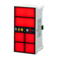
Press SEL button, window 1 will glow. By pressing NC/NO button, the Red LED
can be toggled from ON to OFF and vice versa. If the RED LED glows. Normally
open is a healthy condition & fault sensing is closed type. If RED LED is OFF
Normally closed is a healthy condition & fault sensing is open type.
By pressing T/NT button, the GREEN LED can be toggled from ON to OFF and
vice versa. If the GREEN LED glows the output is programmed for ALARM
RELAY and if the GREEN LED is OFF the output programmed is for TRIP
RELAY.
Press SEL button, now the second window shall glow and by pressing the NC/NO
and T/NT buttons required fault input sensing and relay output can be
programmed. Follow the above procedure for the rest of the windows.
Once the programming of all the windows is over, remove short at “PGM
ENABLE” terminals, to save the program Slide the RUN / PROG switch to RUN
Mode.
HINTS ON CORRECT USAGE
Use proper gauge wires for connections.
Ensure all terminals are tightly screwed.
Source Voltage should not exceed specified limits. It will damage the unit
beyond repair.
CAUTION
Applying power to “PGM
ENABLE”, MUTE, ACK, RST,
TEST & F1-F6 shall damage
the product permanently.
Blinking of unit indicates over
voltage. Switch off the unit for
20Sec to reset the resetable
fuse & switch on.
Applicable for Aux supply 85 to
270V AC/DC only
DISPOSITION
Once the product life is over, you
may send back the unit to EAPL for
disposition.
TROUBLE ANALYSIS
Pilot LED not blinking.
Check power supply (Rated
supply
should be applied).
Fault not sensing.
Check for proper connection
between Common & fault
terminals
(F1-F6).
CONTACT
Electronic Automation Pvt. Ltd
#20, KHB Industrial area
Yelahanka
Bangalore -64
Ph:+91-80-28567561/2/42802345
Email : info@eaplindiamail.com
www.eaplindia.com
Page 3 of 3
 Loading...