EAPL
Model
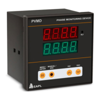
PVMD V3.0
PHASE AND VOLTAGE
MONITORING DEVICE
www.eaplindia.com
DIMENSION
FRONT VIEW
CONNECTIONS REAR VIEW
FUNCTION
Self powered device, Displays 3 Phase voltages (L-N& L-L)
during healthy condition.
Monitors the Phase sequence, Phase failure, Phase
unbalance, over voltage and under voltage in 3 Phase 4 wire
system.
PROGRAMMING
Short 5&6 for program lock.
Top
Display
Shows
Press “MENU”
button, Bottom
Display shows the
following.
Press INC/DEC key to set
the values of parameters .
415 “nUOL”
Nominal voltages
05 “OUOL”
Over Voltage.
Range: 5 to 100V
05 “UUOL”
Under voltage.
Range: 5 to 100V
20 “ PUbl”
Phase Unbalance.
Range: P 1-20%
5 “ tdOV”
Trip delay OverVoltage.
Range: 1 - 250sec
5 “ tdUV”
Trip delay Undervoltage.
Range: 1 - 250sec
5 “tdUb”
Trip delay Unbalance.
Range: 1 – 250sec
bYPS “OVL Y/n”
Bypass Over Voltage
bYPS “UVL Y/n”
Bypass Under Voltage
bYPS “UBL Y/n”
Bypass Phase Unbalance
CntL “rLY Y/n”
When rLY ‘Y ‘ is selected
relay will be ON i.e. ( C to
NO) . When fault occurs
relay goes OFF i.e. (C to
NC).
When rLY ‘n’ is selected
relay will be OFF i.e.(C to
NC). When fault occurs
relay goes ON i.e. (C to NO
RUN MODE
A power ON delay is seen. During this state the
relay will be in NC condition and Relay status
LED will be Off.
Top window will display voltages and Bottom
window will display respective parameters.
In manual mode, the relay will energize and
change over takes place to NO and relay status
LED comes ON only when the user presses the
ESC/Manual button. Till such time the relay
status LED will be OFF.
In Auto mode ( i.e short 6 & 7 terminals), the
relay will energize, change over takes place to
NO and Relay status LED will come ON
immediately after the power ON time is over.
When fault occurs refer the following table:
Parameters Top
display
Bottom
display
OVER VOLTAGE Err OUOL
UNDER VOLTAGE Err UUOL
PHASE UNBALANCE Phs UbAL
PHASE REVERSE Phs rEU
R PHASE FAIL FAIL P-r
Y PHASE FAIL FAIL P-Y
PHASE FAIL FAIL P-b
PHASE UNBALANCE CONDITION:
To set unbalance condition for 20% .
Set 20 in unit (PUbL=20 as shown in the table).
If RY=350V, YB=450V, BY=319V in the load.
Fault is created in the unit , upper displays
shows “Phs” and lower shows
“UbAL”.
Calculations are as follows
Set nVOL=415V , PUbL=20% in the unit.
Vry=350V, Vyb=450V, Vbr=319V , Vavg= 373V
Vry -Vavg=23V, Vyb -Vavg=77V,Vb-Vavg=54V
Phase unbalance= (Maximum deviation / Vavg) * 100 = 20 %
.
DOC NO: OD RE YN 21005 0 Rev No: 05 Dtd: 16/03/2015