Do you have a question about the East Tester ET5406A+ and is the answer not in the manual?
Summarizes user-friendly design, high performance, and safety features.
Details power supply, display, operating conditions, and physical dimensions.
Lists essential items included with the product.
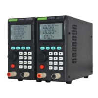
Explains the segment codes and display elements on the front panel.
Identifies and describes the function of each button on the device's front panel.
Guides users on how to select different operating modes like CC, CV, CR, etc.
Explains how to switch between high and low ranges for voltage and current.
Details how to activate or deactivate the instrument's channel.
Describes how to switch between remote and local control modes.
Covers accessing and performing various system settings.
Explains the Constant Current mode, its operation, and display.
Describes the primary display screen for CC mode.
Details how to edit parameters like current setting and delay time in CC mode.
Explains how to view operational status and edit parameters when the channel is active.
Explains the Constant Voltage mode, its operation, and display.
Explains the Constant Power mode, its operation, and display.
Explains the Constant Resistance mode, its operation, and display.
Describes the main display for dynamic test operation.
Details how to edit parameters for dynamic testing when the channel is inactive.
Explains the display interfaces for LIST test when the channel is deactivated or activated.
Details how to edit LIST test parameters when the channel is inactive.
Describes the basic electrical parameters display during SCAN test.
Details how to edit scan parameters like type, start/end values, and step.
Explains the display of basic parameters and battery measurements.
Details how to edit battery test parameters like discharge modes and cut-off conditions.
Lists protection types (OC, OV, OP, OT, RV) and their reasons.
Explains how the keyboard lock function is triggered and how to unlock it.
Describes the available communication ports like USB, RS232, RS485.
| Brand | East Tester |
|---|---|
| Model | ET5406A+ |
| Category | Measuring Instruments |
| Language | English |