Do you have a question about the Eastwood VERSA-CUT and is the answer not in the manual?
Details the duration of the warranty for materials, workmanship, and defects.
Outlines the requirements for obtaining warranty service, including contacting Eastwood.
Explains Eastwood's procedure for determining and executing warranty repairs.
Specifies that the purchaser is responsible for shipping costs to and from Eastwood.
Defines the scope of liability and exclusions for Eastwood's warranty.
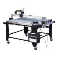
Comprehensive list of all parts, hardware, and accessories included with the CNC plasma table.
Emphasizes thoroughly reading and understanding the manual before operating the equipment.
Guidance on selecting an appropriate, safe, and well-ventilated area for the table.
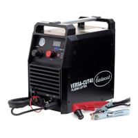
Instructions for connecting the compatible Eastwood Versa-Cut 40 Plasma Cutter to the table.
Detailed explanation of the elements and functions displayed on the main operating screen.
Configuration of machine limits, stepper motor settings, and other system parameters.
Specific settings related to plasma cutting parameters and torch height control.
Explanation of the dynamic elements and status indicators shown during active cutting.
Addresses problems with the control unit not powering on.
Solutions for when the plasma arc fails to initiate correctly.
Troubleshooting for a plasma arc that repeatedly stops or breaks during cutting.
Diagnosing and resolving problems related to the quality of the cut.
Addressing inconsistencies in the dimensions of the cut parts.
Resolving issues with random limit alarms and USB drive detection.
Step-by-step process for selecting and cutting pre-loaded shapes.
Methods for running simulations and testing cut paths without activating the plasma.
Procedures for restarting a cut that was stopped before completion.
Steps to resume cutting after the program has finished prematurely.
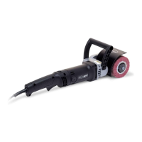
List of essential accessories recommended for research and development use.
| Amperage Range | 20-40 A |
|---|---|
| Input Phase | Single Phase |
| Weight | 21 lbs |
| Gas Type | Compressed Air |
| Frequency | 50/60 Hz |
| Cutting Capacity | 3/8 in |
| Cable Length | 6 ft |
| Warranty | 3 years |