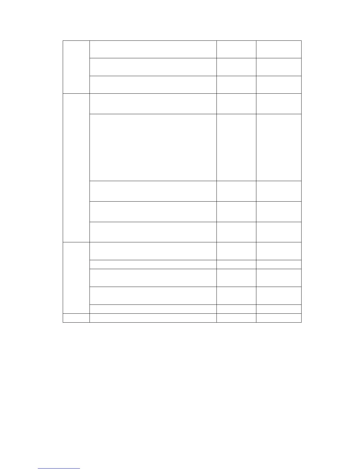
Q13, Q14 MOSFET
D-S short or
open
U7 Photo coupler
Input and output
short or open
R136,R144,R143,R130,R129,R141,R145,R139,R137
,R125,R126,R138,
Resistance Short or open
INV
D3, D4, D5, D6, D7, D8, D12, D13, D15, D16
Diode Short or open
R42, R43,R48, R54, R56, R60, R193, R194, R182,
R210, R208, R209, R78, R83, R87, R95, R49, R55,
R57, R61, R77, R82, R86, R94, R59, R157, R177,
R179,R88,R180,R193,R182,R157,R177,R208,R209,
R179,R180
Resistance Short or open
Q10,Q2,Q16,Q8
Diode Short or open
U1,U2,U3,U4
Photo coupler
Input and output
short or open
QA1, QA2, QB1, QB2, QC1, QC2, QD1, QD2 IGBT
C-E short or
open
MAIN
SPS
Q2 MOSFET
D-S short or
open
D1, D7, D6, D3, D2, D8,D9,D20 Power Diode Short or open
U4 Optocoupler
Input and output
short or open
U3 Control IC
Power Pin and
o/p pin short
R7, R11 Resistance Short or open
AC EMI F1, F2, F3, F4 Fuse Open
Note: If the fuse is in “open” status, don’t replace the fuse only. In most of cases, open
fuse is caused by other failed components. Therefore, before restarting the Inverter, you
must find all failed components and replace them.
Note: Ensure all the failed components have been replaced, then supply the low voltage
and check the control signal. Only when the control signal is OK, you can start the
Inverter.
Note: If all power components function well, and all cables are connected correclty, but
the inverter still can’t start up, we suggest you to replace a new CNTL board.
 Loading...