1. Applications
The easy 3s electronic clock thermostat is designed for room
temperature control in conjunction with:
• heatingsystems,e.g.hot-waterheaters,convectorheaters
or oor heating
• electricconvectorheaters,ceilingandstorageheating
• night-storageheaters
• chillers
• circulationpumps
• burnersandboilers
• heatpumps,etc.
• airconditioningapplications(coolingonly)
Features
•
verysimpleoperation
• comfortandsetbacktemperatureadjustable
•
5operatingmodes(byrotaryswitch)for:
➩permanentcomforttemperature(5…30°C)
➩permanentsetbacktemperature(5…30°C)
➩clockmode(automatic)
➩frostprotection(5°Cxed)
➩ OFF
•
Indicator lamps for: ➩ heat demand
➩setbackmode
•
availablewithdailyorweeklytimer
•
controlbyphoneremoteswitchpossible
•
outputsignal PWM or ON/OFF regulation (adjustable via
jumper)
•
relayoutput,1xchangeovercontact
•
remote sensor optional
•
emergency operation at sensor failure
•
hingedcover
•
newdesign2000
2. Function description
The clock thermostat is designed to control the room tem-
perature.
In the automatic mode, a changeover is eected between
comfortandsetbackmodebythebuiltintimer.
Optionally remote sensor can be used instead of built-in
sensor.
Insetbackmodethegreenindicatorlamplightsup.
Ifroomtemperaturedropsbelowsetvalue,heatingwillstart,
theredindicatorlampwilllightup.
Indicator lamps
Red indicateswhencontrollerdemandsheat,
Green indicateswhensetbackmodeisactivated.
Red ashingforfailure.Operatingvoltagetobeswit-
chedOFFandONagain.
Controller heat demand at PWM
Ifroomtemperaturedropsbelowthesetvalue,heatingmode
will start. The controller output is in the form of pulses of
varying length (PWM).The length of the pulses depends on
thedierencebetweensetandactualroomtemperature.
The sum of pulse and pause times can be selected with J4
(between10or25min.).
If there are largetemperaturedierences,thecontrollerwill
switch ON or OFF permanent, e.g. when changing over to
temperature setback mode. PWM should only be used for
current≤10A
On
Off
Temperature
10/25 min
set temperature
Fig.1:Characteristic of impulse pause ratio depending on
temperature
Cycle time setting
Forinertapplications(e.g.burners)werecommendthe long
cycletime.
Forquickapplications(e.g.electricdirectheaters)werecom-
mendtheshortcycletime.
Plug-in jumper J4
(rightsideofboard)
Time
Double-polejumper
connection
25 min
(as-deliveredcondition)
Single-polejumper
connection
10min
Heat demand of the controller at ON/OFF regulation
When room temperature drops below set temperature the
output will be switched on, whereas it will be switched o,
whensetvalueisexceeded.
set temperature
temperature
OFF
ON
Hysteresis
Fig.2:ON/OFFregulation
Plug-in jumper J3
(rightsideofboard)
Regulation
Double-polejumper
connection
ON/OFF
Single-polejumper
connection
PWM (asdeliveredcondition)
Phone remote switch (onlyavailableatspecialvariants)
Viaanexternalphoneswitchingdevicethe conroller can be
put into mode of comfort or setback temperature. As long
as contact (terminal 19) is closed, the comfort temperature
will be “used“. This function ist activated in the modes 2
automatic, Ñ setback temperature permanent and P
Frostprotection.
3. Installation
Thecontrollershouldbearrangedinaplacewithintheroom
which:
• iseasilyaccessibleforoperation
• isfreefromcurtains,cupboards,shelves,etc.
• enablesfreeaircirculation
• isfreefromdirectsunradiation
• isfreefromdraughts(e.g.openingofwindowsanddoors)
• isnotaecteddirectlybythesourceofheat
• isnotlocatedonanexternalwall
• islocatedapprox.1,5maboveoorlevel
MountingdirectlyonconduitboxorwithadapterframeARA
easy.
Electric connection
Warning!Disconnectelectriccircuitfromsupply.
Proceed as follows:
• pullotemperaturesettingknob
• pushretaininghookoutwardsusingscrewdriver
• removehousingcover
• make connection in compliance with wiring diagram
(seehousingcover).
• watchnotes
Remote sensor
Having connected the remote sensor, the integral sensing
componentwillbeswitchedoautomatically.
The sensor cable is extendable up to a length of max. 50m.
Pleaseuseatwo-core230Vcablewithacross section of 1.5
mm.
Thesensorcable(F193720)shouldbeinstalledintoaprotecti-
ontube(pocket).Thisfacilitateslaterreplacement.
Incaseoffailure(breakorshort-circuit)thecontrollerswitches
into emergency operation:
atPWM: 30%heatingcapacitiy
at ON/OFF: Relay OFF
Warning! Sensor cables carry operating voltage.
4. Technical data
Temperature setting range:
comfort temperature
setback temperature
frost protection
5…30°C
5…30°C
approx. 5°C xed
Regulation proportional controller
(due to PWM quasi-continuous, see Fig.1)
Cycle period adjustable 10 or 25 min.
(sum of PWM ON and OFF times)
Proportional band 1,5K
Hysteresis ~0,5K, ≤ 10A see Fig. 2
~0,5K at 16A and use with remote sensor
~2,5K, at 16A without remote sensor
ON/OFF regulation adjustable via jumper
Output relay, 1 volt-free* changeover contact
Switching current
Heating
Cooling
10mA…16 A cos ϕ = 1
max. 4 A cos ϕ = 0,6
10mA ...10A cos ϕ = 1
max. 1,5 A cos ϕ = 0,6
Switching voltage 24…250V AC
Mode selector switch comfort / automatic / setback /
frost protection / OFF
Phone remote switch
(as variant)
Input for 230V AC (via an external
phone switching device)
Indicator lamp: red
green
controller demands heat
setback mode
Temperature sensor: internal
Remote sensor
Sensor characteristics
type F190021 (wall mounting)
type F193720 length 4m
both extendable up to 50m
42kΩ at 20°C
26kΩ at 30°C
Range limitation inside setting knob
Clock:
accuracy
switching time setting
power reserve
<10 min./year
every 15 min. with daily timer
every hour with weekly timer
approx. 100 h
Protection class of housing IP 30
Degree of protection II (see Warning 1)
Ambient temperature 0…40°C, without condensation
Storage temperature –25…65°C
Pollution degree 2
Rated impulse voltage 4 kV
Ball pressure test
temperature
75 ± 2 °C
Voltage and Current for the
for purposes of interfernce
measurements
230 V, 0,1 A
Dimensions 160 x 80 x 36 mm
Weight approx. 220 g
Energy class IV = 2 %
(acc. EU 811/2013, 812/2013, 813/2013, 814/2013)
* The volt-free contact of this mains-operated unit does
not ensure the requirement for the use of safety ext-
ra-low voltage (SELV).
For units with 230 V supply voltage
Type easy 3st with daily timer
easy 3sw with weekly timer
Article-Nr. easy 3st 517 2701 51 100
easy 3sw 517 2702 51 100
Operating voltage 195…253 V AC 50/60 Hz
Power consumption < 1,5 W
For units with low voltage output
Type easy 3st 1mA with daily timer
easy 3sw 1mA with weekly timer
Article No. easy 3st 1mA 517 2711 51 100
easy 3sw 1mA 517 2712 51 100
Operating voltage 195...253V AC 50/60Hz
Switching current >1 mA, >1V or max. 10(4) A AC
Power consumption < 1,5 W
5. Wiring diagram
Symbol explanation
U Heaing PCooling
Remote sensor
%
Phone remote switch
Note
For heating applications
•connectn/cactuatorstoterminal2.
•connectn/oactuatorstoterminal3.
For cooling applications
• connectn/cactuatorstoterminal3
• connectn/oactuatorstoterminal2
• Tousetheredlampasindicatorfor“coolingON”,connectn/o
actuators to terminal 2
• WhenmodeselectorswitchisinOFFposition
n/c and n/o
actuatorswillbeclosedlogically.
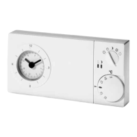
6. Operation
Temperature setting
1
Comfort temperature (daytimetemperature)
issetbymeansofexternallyvisiblesetingknob(1)
2
Setback temperature (nighttemperature)
issetbymeansofadjustmentknob(2)beneathcover.
Time setting
3
byputtingonengerondial(3)andturninginanydirec-
tion,youcansetthetime.
4
Arrow(4)pointstotheselectedtime.
Switching time setting
5
Bringmovabletappets(5)intorequiredpositionusinga
pointedobject.
Outer ring = comfort temperature
Innerring = setbacktemperature
6
Mode selector switch (6)–externally
É Comforttemperature,permanent
2 Automaticmode,time-controlledchangeover
betweencomfortandsetbacktemperature
Ñ Setbacktemperature,permanent
P Frostprotection,permanent(5°C)
OFF,thereisnocontrolactivity.Thecontrolleritselfisnot
disconnectedfromoperatingvoltage.
12
4 5 6
3
U468 931012 911-08
Installation and
Operation Instructions
Electronic
Clock Thermostat
easy 3s
Warning!
Thedevicemay onlybeopenedandinstalled accor-
ding to the circuit diagram on the device or these
instructions by a qualied electrician. The existing
safetyregulationsmustbeobserved.
Appropriate installation measures must be taken to
achievetherequirementsofprotectionclassII.
This independently mountable electronic device is
de-signedforcontrollingthetemperatureindryand
enclosed rooms only under normal conditions. The
device conrms to EN 60730, it works according
operatingprinciple1C.
This product should not be disposed of with
householdwaste.
Please recycle the products where facilities for
electronic waste exist. Check with your local
authoritiesforrecyclingadvice.