Do you have a question about the Eaton APS3-300 and is the answer not in the manual?
Defines the guide's content and intended users, covering installation and operation.
Lists supplementary documents and provides contact details for further assistance.
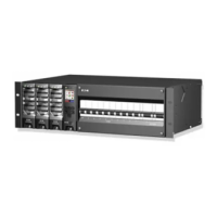
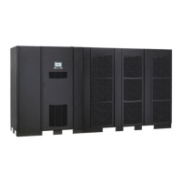
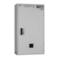
Describes the physical layout and components of the APS units, including front and rear views.
Details rectifiers, system controllers (SC200/SC100), and I/O boards, explaining their functions.
Covers additional functionalities like external communications, LVD, and battery monitoring.
Covers critical safety warnings for electrical hazards, environment, polarity, and component handling.
Guides on inspecting equipment upon arrival and reporting any damage encountered.
Lists the sequential steps required for the physical installation of the APS system.
Highlights crucial tasks like AC supply checks, APS preparation, and cable connections.
Lists the sequence of tasks to bring the APS system online and operational.
Covers inserting rectifiers, pre-power checks, applying AC power, and configuring the system.
Explains configuration files, backup, restore, and identity information.
Covers starting the controller, keypad/PC operation, access security, and alarms.
Guides to diagnose and resolve common system issues, controller problems, and component failures.
Details steps for replacing rectifiers, MCBs, system controllers, and I/O boards.
Covers battery monitoring, mid-point alarms, and proper battery disposal procedures.
Lists required safety equipment, essential tools, and recommended tools for system setup.
Details operating conditions, dimensions, weight, input/output voltage, and power.
Provides specifications for rectifiers, I/O board digital inputs/outputs, sensors, LVD, and communications.
Lists minimum cable sizes for 18mm and 27mm DIN rail MCBs.
Illustrates the menu structures and navigation for the SC200 and SC100 system controllers.
Details pin assignments for RS232, Ethernet, RXP, and USB connectors on the system controller.
Provides pin assignments for various connectors on the I/O board, including LVD, sensors, and digital I/O.
Explains the need for transient protection against over-voltages and the importance of proper earthing systems.
Details recommended primary transient protection at AC supply and secondary protection for the system.
Mentions the transient protection integrated into Eaton rectifiers.
Explains the recommended method of bonding AC and DC earths to prevent voltage differences during surges.
Describes the procedure for isolating AC and DC earths if required, including removing the link.
Lists essential tests for verifying system operation after installation, covering inputs, controls, and alarms.
Details tests for system controls, alarms, analog/digital inputs, and outputs.
Lists contact details for worldwide sales offices and technical support.
| Model | APS3-300 |
|---|---|
| Wattage | 180W |
| Output Power | 180W |
| Input Frequency | 50/60 Hz |
| Output Power Factor | 0.6 |
| Topology | Standby |
| Form Factor | Tower |
| Type | Uninterruptible Power Supply (UPS) |
| Power Rating | 300VA |
| Input Voltage | 120V |
| Output Voltage | 120V |
| Output Receptacles | 6 NEMA 5-15R |
| Battery Type | Sealed Lead Acid |
| Operating Temperature | 0°C to 40°C |