EasyManua.ls Logo

Eaton AT2P - User Manual

Eaton AT2P
12 pages
Print Icon
To Next Page IconTo Next Page
Loading...
AT2P
Digital Quartz Timer
Specifications
Technical Data
Direct mounting onto 35mm din rail.
Optional wall surface-mounting set for 2-3 module
spacing
BS5584
Fully programmable 2 channel 2 modules.
Occupying 2 x 18mm modules
Eaton Electric Limited
Reddings Lane
Birmingham, B11 3EZ
United Kingdom
Tel: 08700 545 333
Fax: 08700 540 333
www.eatonelectrical.com
2007 Eaton Electrical Limited
All rights reserved
May 2007
Ref. Description
AT2P Digital Quartz Timer Fully Programmable , 2 module, 2 channel
Ordering Information
Details
Dimension (H x W x D) mm 45 x 36 x 60
Distributor cut-out mm 46 x 36
Weight g (approx.) 170
Switching capacity at 230 V AC
-ohmic load (VDE, IEC) 16A/250 V AC
-inductive load cos φ0.6 2,5 A/250 V AC
-glow lamp load 1000 W
Switching contacts 1 or 2 changeover
contacts
Running accuracy + 2.5s/day at + 20
0
C
Running reserve type Lithium
Running reserve 150
Shortest switching time 1 minute
Programmable every minute
Memory locations 20/30
Switching pre-selection yes
Hand switch Automatic-pre-selection
Fix ON
Switching state display yes
Block formation of weekdays fixed assignment
Summer/winter time switchover automatic/freely
selectable
Connection type captive +/- screw
terminals
Ambient temperature -25
0
C … + 55
0
C
Led sealable yes
Question and Answer IconNeed help?

Do you have a question about the Eaton AT2P and is the answer not in the manual?

Overview

The Eaton AT2P Digital Quartz Timer is a fully programmable, 2-channel, 2-module device designed for precise time-based control in various applications. It can be directly mounted onto a 35mm DIN rail, or optionally, a wall surface-mounting set can be used for 2-3 module spacing. The device complies with BS5584 standards.

Function Description:

The AT2P timer allows users to set switching times and states for two independent channels. It supports various operating modes for summer/winter time changeover:

  • Automatic Summer Time Controller Switchover (AU): The device automatically switches based on dates defined by legislation.
  • Weekday-Related Summer Time Controller Switchover (cHA): Users can manually enter the start and end dates for summer time applicable to their specific location or country. For example, the first Sunday in April for the start and the last Sunday in October for the end of summer time. In subsequent years, the changeover will occur on the correct day of the week in the corresponding calendar week.
  • No Changeover (no): The timer operates solely as a weekly time switch without any automatic summer/winter time adjustments.

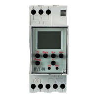
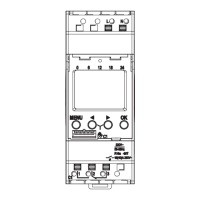
The timer features a clear display that shows the date, summer time status, AM/PM, current time (hours, minutes, seconds), DCF 77 reception status, channel status (ON/OFF), switching state, and operating mode. Control elements include buttons for program input, setting time, selecting days, deleting switching times, and adjusting hours, minutes, month, and year. A hand switch allows for manual override of the current switching state while preserving the programmed schedule.

Important Technical Specifications:

  • Dimensions (H x W x D): 45 x 36 x 60 mm
  • Distributor Cut-out: 46 x 36 mm
  • Weight: Approximately 170 g
  • Switching Capacity (at 230 V AC):
    • Ohmic load (VDE, IEC): 16A/250 V AC
    • Inductive load (cos φ0.6): 2.5 A/250 V AC
    • Glow lamp load: 1000 W
  • Switching Contacts: 1 or 2 changeover contacts
  • Running Accuracy: +2.5s/day at +20°C
  • Running Reserve Type: Lithium
  • Running Reserve: 150 hours
  • Shortest Switching Time: 1 minute
  • Programmable: Every minute
  • Memory Locations: 20/30
  • Switching Pre-selection: Yes
  • Hand Switch: Fix ON
  • Switching State Display: Yes
  • Block Formation of Weekdays: Fixed assignment
  • Summer/Winter Time Switchover: Automatic/freely selectable
  • Connection Type: Captive +/- screw terminals
  • Ambient Temperature: -25°C to +55°C
  • LED Sealable: Yes

Usage Features:

  • Putting into Operation: The time and date are factory-set. The device starts in energy-saving mode with only the colon flashing. Pressing any key activates the time switch.
  • Connections: Numbered terminals at the bottom of the device accept up to 2 x 2.5mm² cables with universal posi/slotted screws and box clamps with cable protector plates. For typical applications, load and timer supply share common connections.
  • Safety Instruction: When operating with safety low voltage, only safety low voltage should be connected. When operating with function low voltage, mains voltage (230V~) or function low voltage can be connected, but safety low voltage is not permissible.
  • Programming: Users can set individual switching times and states for channel 1, channel 2, or both. Block formation of weekdays allows for setting programs for specific days or groups of days (e.g., Monday to Friday).
  • Hand Switch: Provides three modes:
    • Automatic Mode: The switching state corresponds to the entered program.
    • Manual Mode: Allows manual ON/OFF control. The next switching command in the program will be executed automatically.
    • Continuous Operation (FIX): Provides continuous ON or OFF states. To switch back to Automatic mode from continuous operation, the key must be pressed.
  • Read/Change/Delete/Reset:
    • Read: Program contents can be read stepwise, displaying each individual content until the end of the program, followed by free memory locations.
    • Change: Users can navigate to specific switching commands or contents and modify them.
    • Delete Individual: Specific switching commands can be deleted by navigating to them and pressing the Clear key.
    • Delete All: All memory locations can be deleted by pressing and holding the Clear key when "FRxx" (number of max. memory locations) is displayed.
    • Reset: Pressing the Reset key once resets the date and time to factory settings (31.12.1997, 00:00) with automatic summer/winter time changeover (AU) active.

Maintenance Features:

  • DCF Synchronisation: The device supports DCF synchronisation for accurate timekeeping.
  • Power Restoration: In case of mains power restoration, the switching state of the time switch is automatically updated.
  • Suppressor Diodes/Varistors: For large systems, it is recommended to suppress interface voltage on contactor coils switched by the timer using a suitable varistor or RC element. For inductive DC loads, a suppressor diode should be installed. For inductive loads like fluorescent lamps, an isolation relay or contactor is necessary to protect output contacts from heavy strain.

Eaton AT2P Specifications

General IconGeneral
BrandEaton
ModelAT2P
CategoryTimer
LanguageEnglish

Related product manuals