Putting into operation
The time and date are set at the factory.
The time switch is in Energy-saving
mode. Only the colon flashes.
Press any key: The time switch is activated
Safety instruction:
• When operating the clock safety low voltage, only
safety low voltage may be connected.
• When operating the clock with function low voltage,
mains voltage (230 ~) or function low voltage may
be connected. The connection of safety low voltage
is not admissible in this case.
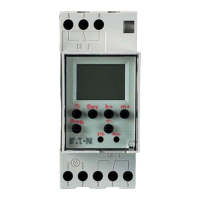
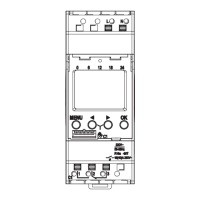
Connections
Numbered terminals are located at the bottom of the
time switch. These terminals have universal posi/slotted
screws, accept up to 2 x 2.5mm
2
cable and feature box
clamps with cable protector plates.
Connection details are: For the typical application where
load and timer supply are common, the following
connections are made:
~
M
1 2
3 4 5
4
~
M
1
2
L
N
LOAD
3
5
N.B.
(a) On large systems it is necessary to suppress the in-
terface voltage on contactor coils which are switched
directly by the time switch using a suitable varistor or
RC element.
(b) If inductive DC loads are switched, it is necessary to
install a suppressor diode.
(c) Inductive loads, particularly fluorescent lamps, repre-
sent a particularly heavy strain for output contacts.
Here it is necessary to install an isolation relay or a
contactor.
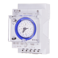
Digital Quartz Timer Product Code: AT2P
 Loading...