2
Current-Limiting – Type NXC® (C-Rated) Fuse
InstallatIon InstructIons MN132014EN November 2016
3.0"
(+
1
/
2
", -0")
Capacitor
NXC Fuse
Bolt or Stud
Mounting
Bus Bar
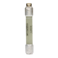
Figure 3. NXC fuse mounted on horizontal capacitor
bank.
4.0"
(+
1
/
2
", -0")
Capacitor
NXC Fuse
Bolt or Stud Mounting
Figure 4. NXC fuse vertically mounted on horizontal
capacitor bank.
ote:N The following recommended spacing between
potentially live elements of a blown fuse and
conductive parts of a capacitor is the same for all
recommended applications of the NXC fuse. Smaller
spacing will result in reduced system BIL after
the fuse has blown. Larger spacing will create an
excessively long fuse leader which could bounce over
and short out adjacent capacitors when it is ejected
from a blown fuse.
5. Secure fuse leader to capacitor bushing connector
and recheck spacing. Leader should be snug and not
contain any slack.
6. Cut off excessive leader wire which extends beyond
capacitor bushing.
ote:N A blown fuse is indicated by the fuse leader hanging
from the capacitor bushing and not connected to the
fuse.
CAUTION
This product as designed and packaged by Eaton
is classified by the USDOT as Not Regulated as an
Explosive. The leader wire must be held in place by
attaching the wire under the hex-head bolt or clamped
to the fuse body to maintain this classification when an
un-operated fuse is transported.
As Shipped from the Factory
Hose Clamp
Figure 5. NXC fuse shown with leader retained for
transportation.

 Loading...


