1
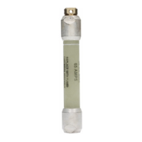
Current-Limiting – Type NXC® (C-Rated) Fuse
InstallatIon InstructIons MN132014EN November 2016
General
Standard safety procedures should be followed when
removing and installing NXC
®
fuses on capacitor blocks.
Removal
1. Remove all power from capacitor block.
2. Allow capacitors to discharge internally for five minutes;
then manually discharge all capacitors, including the
suspected failed capacitor unit.
3. Remove fuse leader from capacitor bushing.
4. Remove fuse from bus bar and retain mounting
hardware for installation of replacement fuse.
Installation
NXC fuses may be mounted by various means on capacitor
blocks. This instruction bulletin provides information for the
four standard configurations as shown in Figure 1 through
Figure 4.
WARNING
NXC fuses should be installed with the leader pointing
down (see Figure 1 through Figure 4).
1. Verify that the proper rated fuse is being installed by
checking information provided on fuse identification
label.
2. Remove leader wire from the hex-head bolt supplied
with the fuse. If a hose clamp is supplied with the
replacement fuse, remove the clamp from the fuse
before fuse installation (see Figure 5).
3. Secure the fuse to the bus bar with the .50-13 UNC-2A
x .75 stainless steel hex reg bolt supplied with the fuse
or use the mounting hardware retained from the fuse
that was removed.
CAUTION
Do not apply any type wrenching tool directly on the
fuse when installing it. Sufficient torque can be applied
with the hand for a proper fit.
4. Check that the recommended spacing exists between
end of main fuse housing and closest conductive part
on capacitor. Refer to Figure 1 through Figure 4 as
applicable.
3.0"
(+
1
/
2
", -0")
Capacitor
NXC Fuse
Bus Bar
Bolt or Stud Mounting
Blown Fuse
Indication
Figure 1. NXC fuse angle-mounted on vertical capacitor
bank.
4.0"
(+
1
/
2
", -0")
Capacitor
NXC Fuse
Bus Bar
Bolt or Stud Mounting
Figure 2. NXC fuse vertically mounted on vertical
capacitor bank.

 Loading...


