

A
Andrew WoodsAug 19, 2025
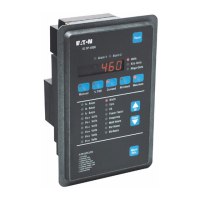
Why are all the operator panel indicators off on my Eaton Cutler-Hammer IQ DP-4000 Monitor?
- CColleen RamirezAug 19, 2025
The operator panel indicators might be off on your Eaton Monitor due to a deficient supply voltage level. Measure the supply voltage and locate the cause of the deficiency. If you are using a separate source or DC source power modules, the control power may be deficient. Locate the cause of the deficiency in the control power line; if the power is sufficient, replace the unit. It is also possible that the AC line, or optional external PTs, are not properly selected, wired, or installed. Verify that the AC line and/or PTs are wired as shown on the wiring plan drawings for the application.