1
INTRODUCTION
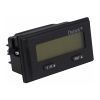
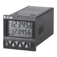
Your 5330X-403 is a counter with an eight-digit LCD
display. A programmable scaler and decimal point allow
for display in any engineering unit.
Durant
®
RST
8-digit LCD
Display
Reset/
Programming
Button
Programming
Button
Plastic
front panel
sealed to
meet
NEMA 4X
Front View
5 Enable/R
5 Enable/R
RST 4
IN A 3
IN B 2
GND 1
6 DC Common
7 +10-30VDC
Program
Enable
Reset Input
Quadrature A
Quadrature B
Ground
Rear View
APPLICATIONS
Certain programming and wiring choices must be made to
accomplish your application. We recommend the follow-
ing sequence:
1. Answer the following questions:
• What type of sensor will be used?
• To what engineering units should the counter be
scaled?
• How many pulses per item is the sensor
providing?
• Is a decimal point needed on the display?
2. Calculate the scale factor.
MOUNTING
PROGRAM MODE
To enter the program mode, a connection must be made
between terminals 1 and 5 (see page 4).
Durant
®
2.677" (67mm)
1.299"
(33mm)
Recommended
Panel Cutout
Dura nt
Install mounting clip
Gasket Installed?
Screens
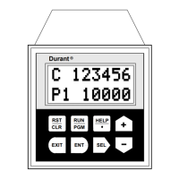
There are four program-mode screens in the 5330X-403.
Upon entering the setup mode, the counter will display
screen 1. Press and hold the
key while repeatedly
pressing the
key to advance to successive screens.
Programming Screens
Screen
1
2
3
4
Function
Count Scale Factor
Count Decimal Point
Reset to Offset Value
Reset Key Enable / Disable
OPERATION
Quadrature Counting
Quadrature is a bi-directional count mode requiring an in-
put signal at each of the totalizer’s two count inputs. Quadra-
ture counting is typically accomplished by using a quadra-
ture encoder as the count source although any two sen-
sors with single channel outputs may be used if the sen-
sors are positioned correctly. In either case, both sensor
outputs must produce pulses at the same frequency and
there must be a phase shift between the signals. The total-
izer recognizes the phase shift and uses it to determine if
it should be counting up, or counting down. Finally, the
signal channels must alternate changes of state. This pro-
duces the four distinct input conditions from which the term
quadrature is derived. These conditions are off-off, on-off,
on-on, and off-on.
Quadrature Signal
Count Inputs
Off
On
Off
On
Count inputs A and B (terminals 3 and 2) are pulled down
to ground (terminal 1). The sensor must supply between
2.0 and 28 VDC at the count inputs for the totalizer to count.
The totalizer has high speed inputs only and is capable of
receiving pulses at 10kHz per channel if each signal is a
square wave and there is a 90° phase shift between the
two signals. For this reason, it is recommended that solid
state sensors (PNP output or NPN output with a pull-up
resistor) be used.
If the totalizer counts in the “wrong” direction at startup,
stop the process and switch the wires at terminals 2 and 3.
This will cause the totalizer to count in the “right” direction
when the process is re-started.