60
Inertia Brake
Inertia Brake
10. Remove the inertia brake electrical connector by removing the two cap screws and gently pulling the connector free
from the inertia brake. (Internal wires must remain attached.)
11. Rotate the connector 180 degrees, so the connector
is facing the speed sensor. (The connector will be pointing up when
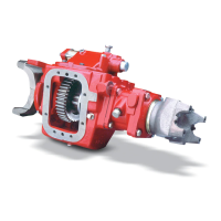
the inertia brake is installed. (See photo for the connector orientation when installed on the transmission.)
Note: C
arefully rotate the connector; do not forcefully twist the wires.
12. Gently guide the wires back into the inertia brake and
install the connector.
Note: Use cautio
n to prevent pinching the wires or damaging the o-ring
Note: Gently guide wires back into the Inertia Brake Housing. Align connector screw holes with housing screw holes and insert
connector into mounting hole. (Note orientation of Connector.) Use caution to prevent pinching of wires or damaging the
o-ring. Reinstall (2) Screws and torque to 22-27 lb-in [2.5-3.1 Nm].
13. Apply thread adhesive to the screws and reinstall. Torque
to 1.84 - 2.28 lb-ft (22-27 lb-in.) (2.5 -3.1 Nm).
Install Inertia Brake on Right Side
1. Apply thread adhesive to (6) mounting bolt threads
2. Using the six mounting bolts, install the new gaskets, spacer, and inertia brake
onto transmission.
Inertia Brake is heavy. Be prepared to handle the inertia brake weight when installing.
Note: If transmission
does not require the spacer, only one gasket is to be installed with the inertia brake.
3. Tighten mounting bolts to 40-45 lb-ft. (54-61 Nm) using a cross pattern
 Loading...