5
Mounting and Operating Instruction GuideLed 10011...11026 LED CG-S 40071860108 (F) www.eaton.com
1.1 Wandmontage Aufputz 10011/11011
(Optional Einbau in Leichtbauwänden)
1.1 Wall mounting, surface 10011/11011
(Optional recessed mounting for lightweigh walls)
1. Aufbau der Leuchte / Maßbilder
20 m
10011/12
11011/12
1101110011
30 m
1. Construction / dimensional drawings
•Die Netzkabel durch die vorgesehene Kabelein-
führung (6) schieben
•Wandmontageadapter mit geeigneten Schrau-
ben an den Befestigungslöchern (4) an der
Wand fixieren (für eventuellen Einbau dieser
Leuchte dienen Befestigungslöcher 2)
•Netzkabel an das Versorgungsgerät an den
Klemmen L und N anschliessen (optional an
die Steckklemme 5)
•Adresse am Versorgungsmodul (7) einstellen
•LED-Anschlussleitung an der Rückwand der
Piktogrammscheibe (8) mit dem Versorgungs-
modul V-CG-SLS 28 (7) verbinden, (2er Steck-
klemme). Bipolarer Anschluss der LEDs - auf
eine Polung muss nicht geachtet werden!!
•Piktogrammscheibe von oben auf die Rück-
wand an den Steckfassungen (3) einschieben
•Zum Öffnen bzw. Lösen der Piktogrammschei-
be das Häkchen (1) zur Seite schieben.
•Feed mains cable through cable entries (6)
•Fix mounting adapter to wall with suitable
screws through fixing holes (4). (For recessed
wall mounting, use fixing holes 2)
•Connect mains cable to supply module at termi-
nals L and N (optional to terminal 5)
•Set the address on supply module (7)
•Connect the LED connection-cable (8),to the
supply module V-CG-SLS 28 (7).Bipolar con-
nection to LEDs - a polarity has not be ob-
served
•Slide the pictogram panel on wall mounting ad-
apter via plug-in sockets (3)
•To open the pictogram panel, push against the
fastening (1).
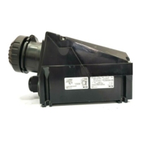
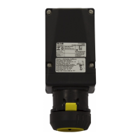
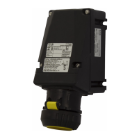
Rückansicht Gehäuse und Piktogramm
Back view enclosure and pictogram
7
4
5
2
3
1
6
6
8
41
33
33
41

 Loading...