Figure 5: Clearance for accessories Note: For high profile (15mm) DIN rail, add 7.5mm to vertical dimension
1
2
3
1
2
Figure 6: Clamping an MTL7700 range of barrier on to a DIN-rail
Figure 7: Removing an MTL7700 range of barrier from
a DIN-rail
250mm
Low-profile rail (7.5mm)
High-profile rail (15mm)
250mm
500mm
Figure 8: Maximum DIN-rail spans between ISP7000 spacers
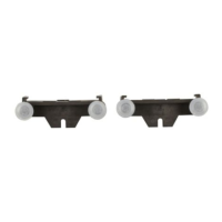
4.3.3 DIN-rail earth terminal (ETL7000)
See figure 10. For those applications (the majority) in which the IS
earth is NOT routed through the mounting surface, connections
for routing the IS earth from the DIN-rail to an appropriate plant
earth are made through earth terminals (ETL7000) clamped onto
the DIN-rail. Two terminals are recommended, one at either end of
a column of barriers, to provide redundancy and to simplify earth
testing procedures.
WARNING: Apart from rare occasions when the mounting
surface carries the IS earth, the ONLY method of providing the
IS earth connection from any one column of MTL7700 range of
barriers is from ETL7000 earth terminals. Never make the plant
IS earth connection to the earth screen on any individual barrier:
this is MANDATORY. See also section 5.3.
ETL7000 terminals are attached to the rail as follows. Ensure the
same security of the earth connection to the rail as for the barriers
themselves (see section 4.2):
a) Hook the fixed end-clamp of the terminal over one flange of
the DIN-rail.
b) Press the body of the terminal downwards until the pivoting
end-clamp engages the other flange of the DIN-rail.
c) Clamp the terminal firmly into place by tightening the centre
screw.
d) Important: wire up the earth terminal as given in section 5.3.2.
 Loading...