EasyManua.ls Logo

Eaton Power Defense PD5 User Manual

Eaton Power Defense PD5
8 pages
To Next Page IconTo Next Page
Page #1 background imageLoading...
Page #1 background image
1
EATON 012410
Instruction Leaflet
Electric current! Dangertolife!
Installation, commissioning and
maintenance workmustbecarriedout
by qualified personnel only.
en
zh
Power
Defense
Breaker IL For Power Defense Frame-5 PDC5 Molded Case Circuit Breaker
IL012410EN
12/23
Minimumclearance/
direction of blow-out
en
zh
25 mm
100 mm
25.4 mm
Picture Shape Size
5 mm
5 mm
3mm8 mm
P1
3 Nm
M5 X 120 mm
90˚
90˚
90˚
90˚
Question and Answer IconNeed help?

Do you have a question about the Eaton Power Defense PD5 and is the answer not in the manual?

Eaton Power Defense PD5 Specifications

General IconGeneral
BrandEaton
ModelPower Defense PD5
CategoryCircuit breakers
LanguageEnglish

Summary

General Safety and Product Overview

General Safety Warning

Warning about electric current and requirement for qualified personnel for installation and maintenance.

Product Identification

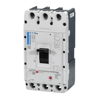
Specifies the Power Defense™ Breaker IL for Power Defense Frame-5 PDC5 Molded Case Circuit Breaker.

Minimum Clearance and Blow-out Direction

Details required minimum clearance and direction of blow-out for the circuit breaker.

Terminals and Connections

Terminal Specifications

Details screw terminal specifications and busbar recommendations for various current ratings.

Barrier Options

Interphase Barrier Options

Illustrates available interphase barrier options for PDC5 circuit breakers.

Settings and Configuration

PXR 25/20 Functions

Describes available functions for PXR 25 and 20 units and refers to the user manual for details.

Accessories

Shunt Trip and Under Voltage Release Installation

Step-by-step guide for installing shunt trip and under voltage release accessories.

Auxiliary and Alarm Switches

Installation of Auxiliary/Alarm Switches

Instructions for installing auxiliary and alarm switches (a, b, c).

Spring Release

Installation of Spring Release

Guide for installing the spring release mechanism (SL5).

Switching Operations Counters

Installation of Switching Counters

Procedure for installing and connecting switching operations counters.

Motor Operator

Installation of Motor Operator

Instructions for installing the motor operator unit.

Electrical Ratings and Diagram

IEC Electrical Ratings

Presents IEC voltage and current ratings for AC-12 and DC-12 applications.

Installation Steps 12 & 13

Illustrates specific installation steps for the breaker.

Testing and Terminal Identification

Test Procedures

Outlines test procedures for energy store, push to close, and push to open operations.

Secondary Terminal Connections

Details the layout and identification of secondary terminal connections for PXR trip units.

Related product manuals