3
Type VFI, Fluid-insulated Switchgear
INSTALLATION, OPERATION AND MAINTENANCE INSTRUCTIONS MN285006EN March 2018
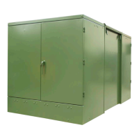
Cabinet construction
Type VFI switchgear features deadfront, tamper-resistant,
low-profile construction. It is suitable for operation in
areas subject to excessive moisture, occasional flooding,
and blowing snow. Cabinets meet the enclosure security
requirements of IEEE Std C57.12.28™-2005 standard.
Top-hinged doors are provided with door stays and fitted
with stainless steel hinges. On units wider than 1168 mm
(46 in), split doors are provided to allow easy operation
by one person. Side-hinged doors can also be provided as
an option. Both source and tap doors can be fully open at
the same time. Each door has a floating lock pocket with
padlock provisions and a pentahead silicon bronze door bolt.
Tank construction is of 7- or 10-gauge steel and cabinets are
made of 12 or 13-gauge steel. Recessed lifting provisions
are provided at each corner of the tank for a balanced lift.
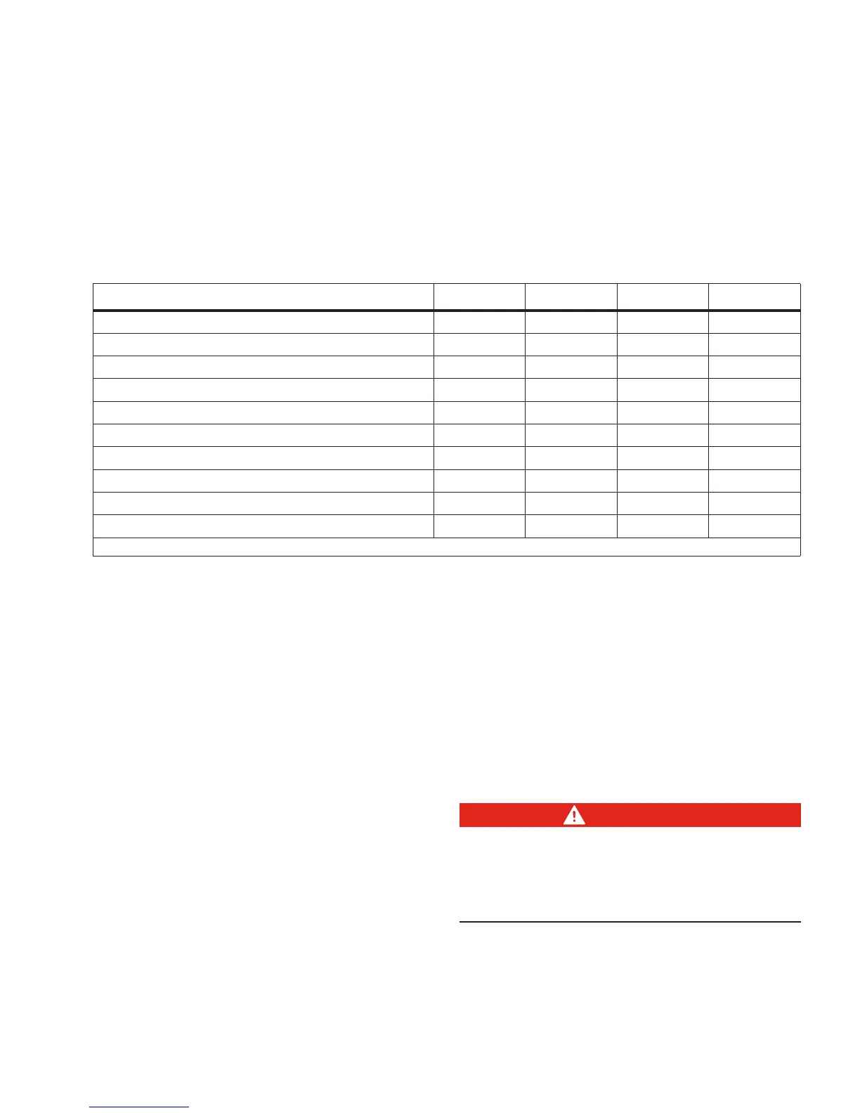
Table 1. Electrical ratings
Rating 5 kV 15 kV 25 kV 35 kV
Maximum Design Voltage, kV
15.5 15.5 27
38
BIL, kV
95 95 125
150
1-Minute Withstand (60 Hz) Interrupter* and Terminators, kV
35 35 60
70
Continuous Current (max), A
600 600 600
600
Interrupting Current (sym./asym.), kA
12/20 12/20 12/20
12/20
Momentary Current 10 cycles (asym.), kA
20 20 20
20
1-Second Withstand Current (sym.), kA
12 12 12
12
Making Current (sym.), kA
12 12 12
12
Transformer Magnetizing Interrupting Current, A
21 21 21
21
Cable Charging Interrupting Current, A
10 10 25
40
* The withstand rating of the switch is higher than that of the connectors per IEEE C37.74
TM
2003 standard.
Padlocking provisions
Provisions are included for padlocking the cabinet in order
to prevent unauthorized door opening. The cabinet must
be locked at all times to prevent accidental contact with
hazardous voltage.
Standard features
Standard features (refer to Figure 2) include a fluid level
indicator, automatic pressure-relief valve, operation one-line
diagrams on the doors, fluid fill plug, fluid drain and sampler
and a standoff bracket for each bushing. Standard ground
provisions include a 1/2-13 UNC stainless steel ground nut
for each bushing.
Interrupter duty cycle
The vacuum fault interrupter mechanism conforms to
the duty cycle requirements of IEEE Std C37.60™-2003
standard.
Switch test sequence
The vacuum fault interrupter operating mechanism conforms
to the switch test sequence requirements of IEEE Std
C37.74™-2003 standard.
Finish
VFI switchgear is finished in a green color which conforms
to Munsell 7GY 3.29/1.5 Green. The coating conforms to
the following specifications: IEEE Std C57.12.28™-2005
standard, ASTM B1117 1000- hour 5% salt spray corrosion
test, ASTM D2247 1000- hour humidity test, ASTM G53
500-hour ultraviolet accelerated weathering test and ASTM
D2794 impact test.
Nameplate
Prior to installation, be sure to check the switchgear
nameplate on the tank front plate in the source side cabinet
to verify that the voltage and current ratings are correct for
the system on which the switchgear is to be installed.
Operating handles
DANGER
Hazardous voltage. Never rely on the open position of
the operating handle or the contact position indicator;
it does not ensure that the line is de-energized. Follow
all locally approved safety practices. Failure to comply
can result in contact with high voltage, which will cause
death or severe personal injury. G123.1