Do you have a question about the Eaton XV-102 and is the answer not in the manual?
Table listing major modifications to the manual.
Explains the information contained in the manuals for correct and safe use.
Instructions for sending comments, recommendations, or suggestions.
Lists additional documentation and resources for hardware, software, and communication.
Describes the use of XV-102 as HMI or integrated HMI/PLC devices.
Specifies the primary use in machine and system building applications for monitoring and control.
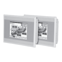
Shows images of different XV-102 device sizes (3.5", 5.7", 7.0").
Detailed table listing device features, interfaces, and part numbers.
Information on ordering accessories and lists accessories for 3.5" devices.
Lists package contents for 5.7" devices.
Lists package contents for 7.0" devices.
General advice on using and ordering accessories.
Details information found on the device's nameplate for identification.
Lists obtained type approvals and conditions for marine applications (DNV GL).
Outlines basic safety principles and the importance of reading the manual.
Explains hazard symbols (DANGER, WARNING, CAUTION) and their meanings.
Outlines requirements for personnel, operating manuals, and disposal.
Lists conditions and responsibilities for safe and compliant device operation.
Details specific hazards like explosion, live parts, stray currents, and ESD.
Covers hazards related to interfaces, sensitive touch, data loss, and condensation.
Covers hazards related to UV light exposure and cleaning procedures.
Identifies and describes the device's operating and indication elements (buttons, display, SD slot).
Directs users to safety regulations before installation and commissioning.
Lists requirements for device placement, power supply, and approvals.
Specifies conditions for mounting location, ventilation, and surface characteristics.
General warnings and considerations for device interfaces and wiring.
Shows images of interfaces for different device models.
Details interface types and their descriptions.
Instructions on preparing screened cables for D-Sub connectors for EMC compliance.
Continues instructions on cable preparation and EMC guarantees.
Details the power supply requirements (24V DC SELV) and wiring for the connector.
Explains the need for radio interference suppression filters for the 24V DC supply.
Describes the RS232 interface, its pin assignment, and baud rate dependency on cable length.
Details the Ethernet interface, LEDs, cable requirements, and forces on the connector.
Describes the USB device interface (Type B) and cable requirements.
Describes the USB Host interface (Type A) and cable requirements.
Introduces the SmartWire-DT Master interface and lists required additional documentation.
Explains the POW/AUX interface, LEDs, and configuration button for SmartWire-DT.
Details the POW/AUX interface, its power supplies, and wiring.
Describes the SWD interface and required ribbon cables for network connection.
Provides steps for initial startup and configuration of the SmartWire-DT network.
Details the configuration check process and LED status meanings for SmartWire-DT.
Describes the CAN interface, its pin assignment, and cable specifications.
Continues CAN interface details with cable specifications and baud rate dependency.
Explains CAN bus topology, termination requirements, and potential transfer errors.
Details the Profibus interface, its pin assignment, and cable specifications.
Continues Profibus interface details with cable specifications and baud rate dependency.
Explains Profibus topology, termination requirements, and potential transfer errors.
Describes the RS485 interface, its pin assignment, and cable specifications.
Continues RS485 interface details with cable specifications and topology.
General warnings about interference and condensation during mounting.
Provides mounting cutout dimensions for 3.5", 5.7", and 7.0" devices.
Details gasket installation, retaining brackets, and the process of mounting the device.
Explains retaining bracket positions for different device sizes and IP ratings.
Continues explanation of retaining bracket positions for 5.7" and 7.0" devices.
Instructions on using ferrite rings to screen communication cables for EMC compliance.
Refers to general safety regulations and highlights touch surface and condensation hazards.
Steps for energizing the device and troubleshooting initial boot issues.
Instructions for de-energizing the device.
Procedures for inserting and removing SD cards, with warnings about data loss.
Refers to general safety regulations and specific maintenance hazards like cleaning.
States that only authorized personnel should open the device for repairs.
Lists common faults and their corrective actions for device operation.
Refers to general safety regulations for handling, storage, and transport conditions.
Warns about explosive/toxic materials and proper device disposal procedures.
Provides mechanical dimensions and weights for 3.5" devices.
Provides mechanical dimensions and weights for 5.7" devices.
Provides mechanical dimensions and weights for 7.0" devices.
Details display properties like resolution, visible area, and color resolution.
Describes the properties of the touch sensor technology.
Lists system properties such as processor, memory, and real-time clock battery.
Lists all available interfaces (Ethernet, USB, CAN, Profibus, RS485, etc.).
Specifies power supply requirements, voltage ranges, power consumption, and current limits.
Details the POW/AUX interface for SmartWire-DT, including voltage and current specs.
Details the SWD interface properties like voltage, current, and baud rate.
Lists the IP ratings for the device's front and rear sides.
Summarizes EMC, explosion safety, UL, and marine approvals for the device.
Lists standards and directives that the device complies with (EMC, ATEX, UL, etc.).
Specifies operating and storage temperature, humidity, and vibration limits.
| Touchscreen | Yes |
|---|---|
| Display Type | TFT-LCD |
| Resolution | 1280 x 800 pixels |
| Interfaces | Ethernet, USB, Serial |
| Mounting | Panel Mount |
| Ingress Protection | IP65 |