September 2012 IPV6865
I/O PINS: 1 .Alarm input 2 Alarm input 3 Alarm output 4 Alarm output
Input pins: The input pins can be used for 1-way external sensor input. For example, you may connect a
Person Infrared Sensor (PIP) to it for motion detection. When external sensor triggered, IP CAMERA can be
programmed to send an email with picture or control the internal relay output.
If you link an external alarm device with Pin3 and Pin4, when select Alarm Input Armed (Figure 10.0), external
alarm is enabled.
Output pins: The output pins can enable IO linkage on alarm.
You can also use
& to control IO output Switch ON/OFF (See Figure 4.4).
NOTE: All the pins work as switch only.
3.19 Send e-mail on Alarm
When chosen, it will send picture and e-mail to your e-mail once alarmed. (First you should finish the e-mail
Service Settings. Figure 9.1).
NOTE: It usually will send 6 snapshots by one e-mail to your mailbox for each alarm triggered. Each alarm will
last for 60 seconds.
Upload Image on Alarm
Enable Upload Image on Alarm to set upload images to FTP once alarmed.
Upload Interval: Set the upload interval (Seconds).
NOTE: The total alarm time is 60 seconds.
Figure 10.4
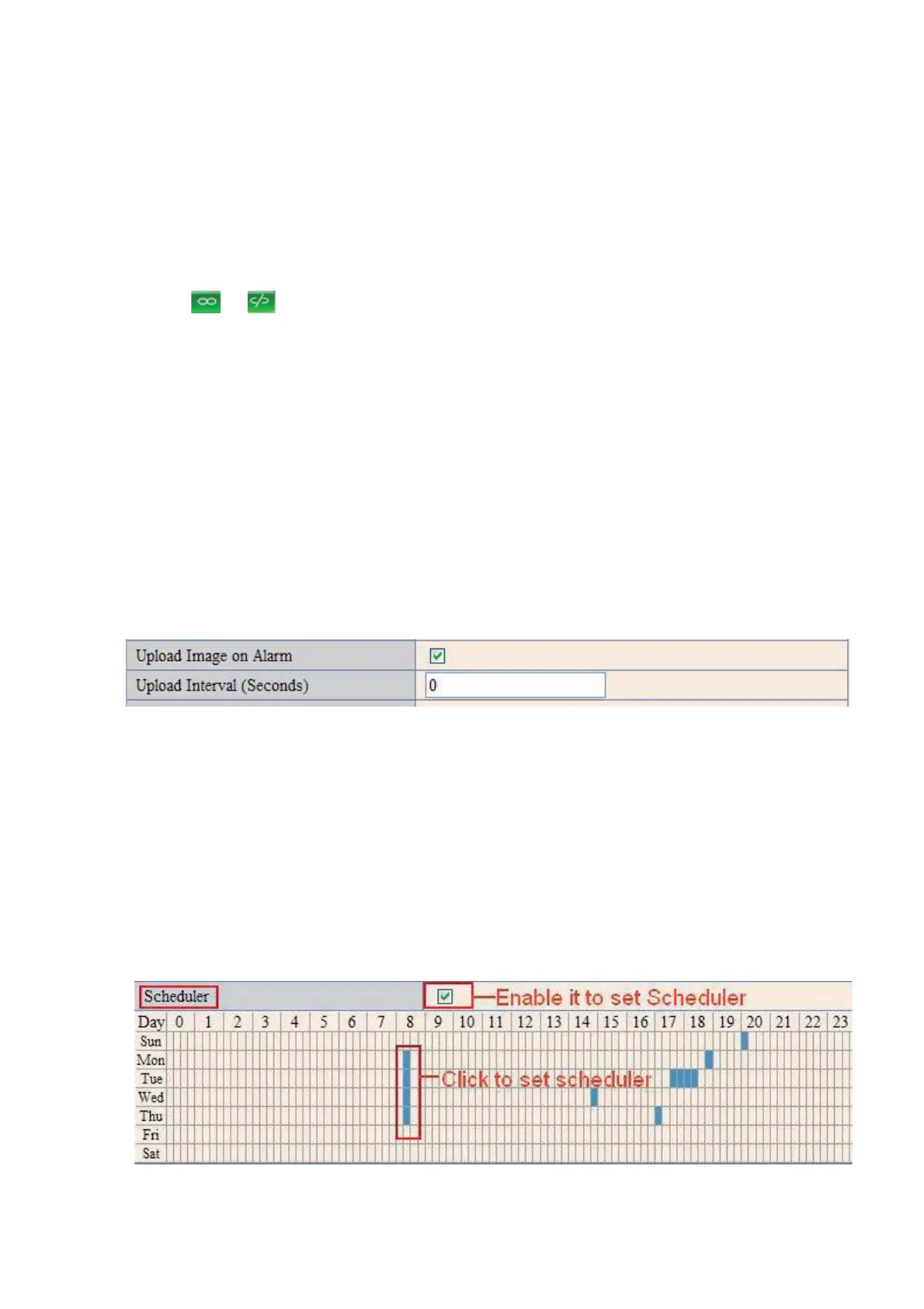
Scheduler
Here you can set the camera alarm during the time you set. Choose Scheduler and set the date & time
range. (Figure 10.5) From Monday to Sunday, and every day divided into 24 hours, each hour divided into 4
quarters.
Left click the frame of the time range, it will turn to blue color, which means the time you choose to be
armed.
Click it again, it will turn back to gray, which means delete the scheduler.
NOTE: Make sure the date & time settings are correct first. (Figure 8.3).
ATTENTION: If you don’t choose Scheduler, the camera will alarm anytime when motion triggered.
Figure 10.5
 Loading...