Do you have a question about the EBRO ARMATUREN EP100 and is the answer not in the manual?
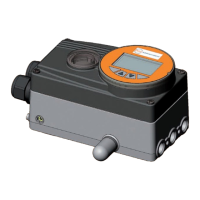
Provides a general overview of the EP100 positioner and its function with pneumatic valve actuators.
Illustrates the functional components and signal flow within the EP100 analog positioner.
Explains how the EP100 processes input signals, controls pneumatic amplifiers, and measures actuator position.
Covers accident prevention, electrical safety, explosion protection, and EMC/CE compliance for the EP100.
Shows an example of the EP100 nameplate with serial number, supply, and input specifications.
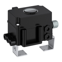
Details pneumatic accessories like boosters and connection manifolds for the EP100 positioner.
Explains how to mount the EP100 to rotary actuators according to VDI/VDE 3845 standards.
Outlines steps for preparing the EP100 positioner, including setting failsafe position and actuator rotation.
Details the preparation steps for the rotary actuator before attaching the EP100 positioner.
Describes how to attach the EP100 positioner to the actuator using a bracket and screws.
Details the wiring connections to the EP100's screw terminals for input signals.
Covers initial checks, prerequisites, and general steps before starting up the EP100 positioner.
Explains how to use DIP switches and potentiometers for configuring the EP100's parameters.
Guides setting the feedback shaft's rotation direction via switches for correct actuator response.
Details how to configure the EP100 to accept various input signal ranges (4-20mA, split range).
Explains configuring multiple positioners for sequential control of a valve stroke.
Describes adjusting the loop amplification (gain) using potentiometer P4 for stable control.
Guides setting the zero and span points of the actuator stroke using potentiometers P3 and P2.
Explains how to adjust damping using potentiometer P5 to influence dynamic behavior.
Details how to set the mechanical travel indicator and select gear ratios.
Describes the function and adjustment of air reducing throttles for output capacity control.
Outlines the procedure for performing basic adjustments on the electronics unit.
Explains how to perform a pneumatic test to check the positioner's system function.
Provides general guidance on maintenance requirements and safety for the EP100 positioner.
Details the procedure for replacing the air supply filter.
Explains how to safely remove the electronics unit from the EP100 housing.
Describes how to convert the EP100 between different positioner types by exchanging electronics.
Guides on replacing the pneumatic amplifier and associated O-rings for the EP100.
Details the process for replacing the preamplifier and its O-rings.
Explains how to replace the IP module, including O-rings.
Describes how to remove and install the feedback unit, including shaft and sensor.
Covers limit switch installation, functions, trigger points, and types (2-wire, 3-wire).
Details the 4-20mA transmitter, including setup, adjustments, and troubleshooting.
Explains direct connection of the EP100 to a standard 4-20mA process control system.
Details system configuration for split range operation with multiple actuators.
| Input Signal | 4 - 20 mA |
|---|---|
| Protection Class | IP65 |
| Type | Electropneumatic |
| Supply Air Pressure | 1.4 - 7 bar |
| Output Pressure | 0 - 100% of supply pressure |
| Ambient Temperature | -20°C to +80°C |
| Housing Material | Aluminum |
| Connections | G 1/4 |