EasyManuals Logo
Home>Ebyte>Motherboard>MBL Series

Ebyte MBL Series User Manual

Ebyte MBL Series
16 pages
To Next Page IconTo Next Page
To Previous Page IconTo Previous Page
Page #5 background imageLoading...
Page #5 background image
Chengdu Ebyte Electronic Technology Co.,Ltd. E32-900MBL-01 User Manual
Copyright ©2012–2019Chengdu Ebyte Electronic Technology Co.,Ltd.
4
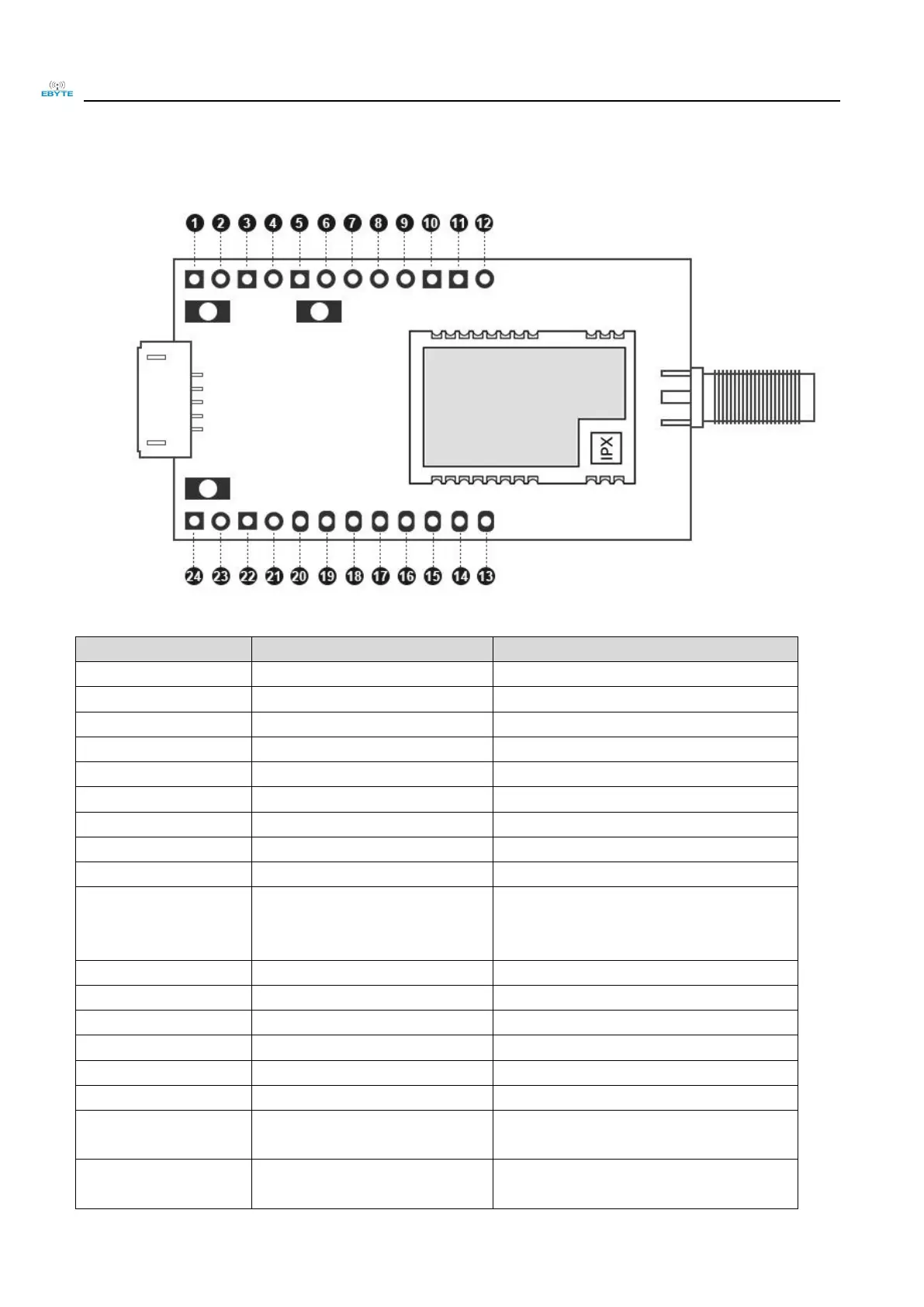
1.2 Size, interface description
No.
Definition
Function Description
1
3.3V
3.3V Electric pin
2
3.3V
3.3V Electric pin
3
GND
Floor reference ground
4
GND
Floor reference ground
5
3.3V
3.3V Electric pin
6
GND
Floor reference ground
7
REST
MCUExternal reset pin
8
SWIM
SWIM pin of MCU
9
3.3V
3.3V Electric pin
10
VCC
Module power supply pin, need to be
short-circuited with pin 9 to supply power to
the module
11
PC6
MCU ordinary IO
12
PC5
MCU ordinary IO
13
PB3
MCU ordinary IO
14
PB2
MCU ordinary IO
15
PB1
MCU ordinary IO
16
PB0
MCU ordinary IO
17
M1
Module mode switch pin (see module product
manual for details)
18
M0
Module mode switch pin (see module product
manual for details)

Questions and Answers:

Question and Answer IconNeed help?

Do you have a question about the Ebyte MBL Series and is the answer not in the manual?

Ebyte MBL Series Specifications

General IconGeneral
BrandEbyte
ModelMBL Series
CategoryMotherboard
LanguageEnglish