IF Series Wiring
An IF series lightbar has a dedicated ground wire and one or more +power wires routed to the modules. The black ground wire should be
connected directly to the battery. The amp ratings for each module type are detailed in the specications section of this installation guide.
Before attempting to connect the lightbar wiring harness, refer to the conguration specic wiring key included with the lightbar for the func-
tions of each wire. Use an appropriate high-temperature wiring if it passes through the engine compartment. Use cable ties and grommets to
secure and protect all cables and wires.
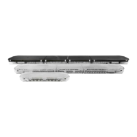
The ash pattern on corner and directional modules can be cycled to the next ash pattern on each individual module by momentarily short-
ing together the JP1 pins with a wire or the blade of a screwdriver (shown below). The light head will reset to the default ash pattern when
the JP1 pins are shorted together for 5 seconds or more and then releasing. Module pairs connected by a sync wire must be individually set
to the same ash pattern to properly synchronize.
FIGURE 7
IF Series Flash Pattern Selection
TABLE 1
Directional and Corner Module
Flash Patterns
Order Flash Pattern
1 Cycle Flash 70 FPM (Default)
2 NFPA Quad Flash 80 FPM
3 Quad Flash 70 FPM
4 Steady Burn
5 Five Flash 70 FPM
6 Triple Flash 70 FPM
7 Double Flash 70 FPM
8 Single Flash 70 FPM
9 Quad Pop Flash 70 FPM
10 Triple Pop Flash 70 FPM
11 Mod Flash
12 Cycle Flash 150 FPM
13 Five Flash 150 FPM
14 Quad Flash 150 FPM
15 Triple Flash 150 FPM
16 Double Flash 150 FPM
17 Single Flash 150 FPM
18 Single Flash 250 FPM
19 Single Flash 375 FPM
 Loading...