Page 2 of 5
1. Find an appropriate location for installation.
2. Drill holes according to the size of U-bracket and x the U-bracket.
3. Drill a 3/4” (19mm) hole next to U-bracket.
4. Install the camera on U-bracket.
5. Connect the camera tail with the extension cable from inside the vehicle.
6. Loosen the screws on the side of the camera and adjust the camera’s position to get the best view angle in the monitor.
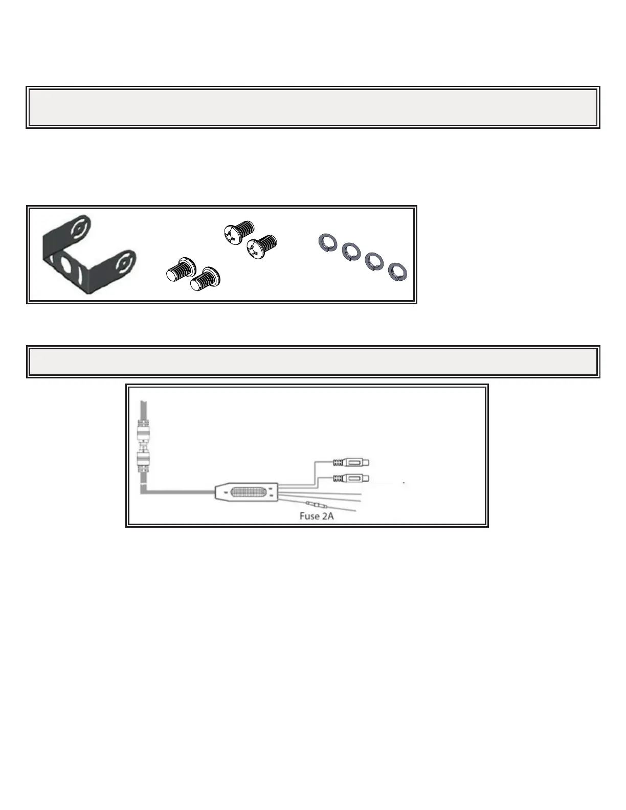
Figure 1
Wiring:
AV1 input
AV2 input (V2)
Trigger Wire (Green) for AV2 only
GND (Black)
DC12V (Red)
Figure 2
Picture depicted is for reference only.
Camera Model C2013B
Installation, Wiring and Function
Installation:
Important! Mount the camera at a location that provides the best view of the area immediately behind the vehicle. Generally, mounting
locations toward the top of the vehicle provide the best eld of view. Lower mounting locations reduce the eld of view and increase the
likelihood of damage from road spray.
Important! Waterproof all connections whether inside or outside the vehicle by using sealant and wrapping with insulation tape. Wrap tape
tightly, overlapping by one-half widths so there are no gaps.