Do you have a question about the ECG AD8232 and is the answer not in the manual?
Overview of the ECG device's hardware components and their connections.
Overview of the software setup required for the ECG device.
Details on adding an RLD resistor for enhanced safety and current limiting.
Guide to creating custom electrodes cables for the device.
Method for connecting GND without soldering using connector cables.
Instructions for integrating a switch and housing the device in a box.
Steps for uploading Arduino sketch files to the board using the IDE.
Guide to installing the ECG SmartApp on a smartphone and pairing.
This document outlines the assembly and software setup for a low-cost, portable ECG device, designed for easy construction and use. It is explicitly stated that this project is not a medical device and should not be used for diagnosis or treatment of any conditions. The device aims to provide a simple and accessible way to acquire ECG signals, emphasizing ease of assembly and basic electronic skills.
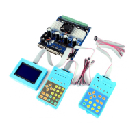
The ECG device functions by acquiring, amplifying, filtering, digitizing, and transmitting electrocardiogram (ECG) signals. It utilizes an AD8232 ECG module to amplify and filter the raw electrical signals from the body, an Arduino board for digitizing these analog signals, and a Bluetooth module (HC-05 or HC-06) to wirelessly transmit the processed data to an Android smartphone. The smartphone then runs a dedicated application, "ECG SmartApp," to display and potentially analyze the ECG waveform.
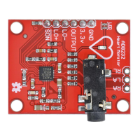
The core functionality revolves around the AD8232 module, which is a single-lead heart rate monitor front-end designed to extract, amplify, and filter small biopotential signals in the presence of noisy conditions. This module is specifically configured to provide a frequency band suitable for ECG acquisition. The Arduino board acts as an intermediary, converting the analog output from the AD8232 into digital data and then relaying it to the Bluetooth module. The Bluetooth module facilitates the wireless communication, enabling the device to be portable and used without direct physical connection to the display unit (smartphone).
The device is designed for straightforward usage, requiring minimal technical expertise once assembled.
Ease of Assembly: The manual highlights that the ECG device can be built easily, typically in less than an hour, and requires only very basic electronics skills. This makes it accessible to hobbyists and individuals with limited experience in electronics. The assembly involves connecting three main modules: the AD8232 ECG module, an Arduino Nano board, and an HC-05/HC-06 Bluetooth module. Connections can be made either by soldering wires directly to the boards or by using connector cables with female headers, offering flexibility based on user preference and skill level.
Power Supply: The device is designed to be battery-powered, specifically recommending a voltage between 6V and 9V. This ensures portability and safety, as it explicitly warns against using AC power supplies, transformers, or any other voltage supply to avoid serious injury and electrical shock. The use of low-voltage batteries is a critical safety precaution. While a 7V battery is recommended for the Arduino Nano, the device can operate with 6V (e.g., 4x 1.5V AA or 5x 1.2V AA rechargeable batteries when fully charged). However, using a higher voltage like 9V is suggested to prevent noisy ECG signals as batteries discharge.
Electrode Connection: The AD8232 module typically comes with an electrodes cable that can be plugged directly into its dedicated connector. For users who prefer a customized solution, the manual provides instructions for making "home-made" electrodes cables using coaxial cable, alligator clips, heat shrink tubing, and female header connectors. This allows for adaptability and potential cost savings.
Software Installation and Operation: No software programming knowledge is required for the user. The "ECG SmartApp" for Android smartphones is installed by simply opening an .apk file and accepting permissions. For the Arduino board, a pre-provided sketch file (ECG_SmartApp_skecht_arduino.ino) can be uploaded using the Arduino Software IDE, following available online tutorials. This simplifies the software setup significantly.
Bluetooth Connectivity: The device connects wirelessly to an Android smartphone via Bluetooth. The initial connection may require a pairing code (defaulting to "1234"). Once paired, this operation is generally only needed once. The HC-06 module's LED can serve as an indicator that the board is powered on, eliminating the need for an additional LED.
Portability: The design encourages housing the assembled components within a box, which can include a switch for turning the device on/off and a battery holder. This makes the device compact and easy to carry, enhancing its portability.
The manual provides insights into potential modifications and considerations that could be seen as maintenance or enhancement features, primarily focusing on safety and adaptability.
RLD Resistor for Safety: A crucial safety feature discussed is the Right Leg Driver (RLD) resistor. The AD8232 uses an RLD to reduce common-mode interference. For safety, the RLD output is connected to the electrode through a protection resistor. Standard AD8232 modules typically use a 360 kOhm resistor. However, to ensure the RLD current limit remains below 10 µA, especially when using higher battery voltages (e.g., 6V or 9V), a higher resistance is needed. The manual suggests replacing the 360 kOhm resistor with a 680 kOhm resistor for a 6V battery or a 1 MOhm resistor for a 9V battery. This modification requires some soldering skill due to the small size of SMD resistors.
Alternative RLD Resistor Implementation: As an easier alternative to replacing the SMD resistor, a common through-hole resistor (e.g., 330 kOhm for a 6V battery or 680 kOhm for a 9V battery) can be added in series with the existing 360 kOhm resistor. This can be achieved by placing the additional resistor between the RL pin of the AD8232 board and the RL electrode, though this would necessitate using the electrodes pins rather than the AD8232 plug-in connector. This offers a less skill-intensive option for maintaining safety.
Alternative GND Connection: To avoid direct soldering for GND connections, especially since the Arduino Nano has only two GND pins, the manual suggests a solution using connector cables. One GND pin can connect to the battery negative terminal, and the other can be connected to both the AD8232 and HC-06 GND pins via a connector cable setup. This simplifies assembly and potential troubleshooting.
Compatibility with Other Arduino Boards: While the provided Arduino sketch is optimized for Arduino Nano and UNO, the device can potentially work with other Arduino boards like Arduino Micro or Mega. However, using different boards may require modifications to the sketch file to adapt to their specific features. This indicates a degree of flexibility and potential for future upgrades or adaptations.
HC-05 Module Compatibility: The device is also compatible with the HC-05 Bluetooth module as an alternative to the HC-06, offering flexibility in component sourcing.
Box and Switch Integration: The inclusion of a switch through the battery's positive terminal allows for easy power control, contributing to battery life and convenient operation. Designing a box with specific holes for the switch, electrodes cable, and an optional LED (or using an existing LED on one of the boards) helps protect the components and provides a professional finish, which can be considered a form of physical maintenance or enclosure management.
| Supply Current | 170µA |
|---|---|
| Common-Mode Rejection Ratio | 80dB |
| Operating Temperature Range | -40°C to +85°C |
| Type | Instrumentation Amplifier |
| Chip | AD8232 |
| Output | Rail-to-Rail |
| Input Impedance | 10GΩ |
| Gain | 100 |
| Bandwidth | 0.5Hz to 40Hz |
| Input Bias Current | 1 pA |
| Quiescent Current | 170µA |
| Package | LFCSP |