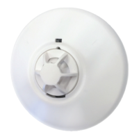
220~240V AC
INTERCONNECTABLE
HEAT ALARM
(FIXED TEMPERATURE TYPE )
M
ODEL: E240VHD
(
With 9V Battery Back-up)
Main Features:
Test Button
Low Battery Warning
Battery Back-u
p
Alarm / Power Indicator
Interconnectable (Up to 20 Heat and
Smoke Alarms)
Supplied with Fixing Kit
Loud 85 dB Alarm Signal
This instruction leaflet contains important information on the
correct installation and operation of your heat alarm. Read this
leaflet fully before attempting installation and retain for future
ref
erence.
SPECIFICATION
Power Source:
Battery Back-up:
Battery Back-up Life:
Operation Current : <40mA operation (In Alarm)
Temperature Rating : 60ºC Fixed temperature only
Maximum Ambient : 40
o
C
Recommended Spacing : 13.5m
Alarm Sound Level : 85 Decibels at3 metres (10 ft.)
LOCATING THE ALARMS
Heat Alarms are intended to be supplementary to Smoke Alarms
and should only be placed in areas where smoke alarms cannot be
used.
This heat alarm is a multiple station heat alarm and can be
connected to other alarms of the same
make and type. This
interconnect feature allows up to 20 Heat Alarms and / or Smoke
Alarms to be connected together over 150 metres maximum, using
the
single white wire, and thus allowing all alarms
to sound when
any one is activated.
This Heat Alarm cannot be connected to any other device such as a
fire alarm
panel.
This Heat alarm
gives a fire warning when the temperature at the
unit reaches 60ºC. It is ideal for kitchens, garages, cellars, boiler
rooms, attics and other areas where there are normally high levels of
fumes, smoke or dust which preclude the use of Heat Alarms
due to
the risk of false alarms.
All the Heat Alarms and Smoke Alarms
should be interconnected to
ensure the early warning will be heard, particularly by somebody
sleeping. A properly designed early warning fire system ensures
the alarm is given before the escape routes become blocked with
smoke. Therefore there must be Smoke Alarms along the escape
routes as Heat Alarms would not give sufficient warning. However, a
f
ire in a closed room (e.g. kitchen) adjoining the escape route, can
eventually cause the corridor to become smoke-logged due to smoke
leaking out from around the door before adequate warning can be
given by detectors in the corridor. A heat Alarm in the closed
room may give early warning of fire in that room.
If your dwelling is on a single storey, for minimum protection you
s
hould fit a Smoke Alarm in a corridor or hallway between the
sleeping and living areas. Place it as near to the living areas as
possible and ensure the audible alarm can be heard when the
bedrooms are occupied. See Figure 1 for examples.
If your dwelling is mu
lti-storey, for minimum protection one Smoke
Alarm should be fitted at the bottom of the staircase with further
alarms
fitted on each upstairs landing. This includes basements but
excludes crawl spaces and unfinished attics. See Figure 2 for
examples.
FIGURE 1 – SINGLE STOREY DWELLING
FIGURE 2 – 2/3 STOREY DWELLING
POSITIONING THE ALARMS
Ceiling Mounting
As hot smoke rises and spread out, it is advisable to mount on
a ceiling in a central position. Avoid areas where there is no air
circulation, e.g. corners of rooms
and keep away from items
which may prevent the free flow of air. Place the unit at least
300mm from and light fitting or decorative object which might
obstruct smoke / heat entering the alarm. Keep at least 300mm
away from walls. See Figure 3i.
Wall Mounting
D
o not mount tight into the corners. Put the top edge of your
heat alarm between 150 and 300mm
below the ceiling.
Keep at least 300mm from room corners. See Figure 3i
(Wall mounting is not recommended for Heat Alarms)
On a Sloping Ceiling
In areas with sloping or peaked ceilings install your Heat
Alarm
900mm from the highest point measured horizontally
because “dead air” at the apex may prevent smo
ke from
reaching the unit. See Figure 3ii.
Areas to be avoided include the following :-
Situations where the temperature m
a
y fall below 4
o
C or rise
above 40
o
C
Humid areas such as bathrooms, kitchens, shower
rooms where the relative humidity may exceed 90%
Near a decorative object, door, light fitting, window
molding etc., that may prevent sm
oke or heat from entering
the alarm.
A
djacent to or directly above hot components such
as radiators or wall vents that can effect the direction
of air currents.
In very dusty or dirty environments such as workshops.
Locate unit at least 1.5m and route wiring at least 1m away for
fluorescent light fittings as electrical “noise” and/or flickering
may affect the unit. Do not wire into the same circuit
as
fluorescent lights or dimme
rs.
Do not locate in insect infested areas. Insects and
contamination on the Heat Alarm sensor can increase its
response time.
INSTALLING THE HEAT ALARM
WARNING – This heat alarm is mains powered and requires wiring
by a qualified electrician in accordance with the current
IEE Regulations for Electrical Installations (BS7671).
The circuit used to power the heat alarm
must be a dedicated
permanent supply that cannot be switched off accidentally by the
normal user. Before installing ensure the electrical supply is isolated.
WARNING : To prevent injury, this heat alarm must be securely
attached to the ceiling/wall in accordance with the installation
instructions.
The Heat Alarm
will function correctly either as a stand-alone alarm
or inter-connected.
All inter-connected Heat Alarms
must be supplied from a single
power circuit.
A common neutral must be used for the interconnect to function.
Do not connect the Inter-connect wire to Live or Neutral.
Figure A
! Important ! A correct AC Quick Connector Plug should have a
Brown, Blue, White wire on it as the configuration on Figure A
above. If the AC Quick Connector Plug does not have the
correct color order, please STOP USING IT and contact your
retailer store immediately to replace for a new AC Quick
Connector.
Disconnect the AC main power from the circuit that is going to be
used.
Having established the mounting location install a junction box
suitable for locating the termination point. Ensure that there is
no other electrical wiring or pipe work in the area adjacent to
the mounting surface.
Unlock the detector unit from the base by
push back the snap
lock with a screw driver and turn the alarm
unit anti-clockwise to
release it. See Figure 5 and Figure 6
Fix mounting plate in position.
Strip the Live / Neutral and Interconnect (if used) wires.
Connect the wires correctly. If the heat alarms are to be
interconnected, connect the white wire. For Alarm that are used as
single station, DO NOT CONNECT THE WHITE WIRE TO
ANYTHING. Ensure the screws are fully tightened. See Figure 6.
The alarm must be wired in accordance with National wiring
codes.
KM 672401
BS 5446-2:2003
Detector Classification A1
Figure 3i - Positioning the smoke / heat detector Figure 3ii
CEILING
30 cm
BEST IN CENTRE OF ROOM
15cm Min.
Do not mount lower
than 30 cm
DEAD AIR SPACE,
Do not mount
within this area
WALL
900 mm
(3 ft)
220-240Vac~ 50-60Hz with 9V battery
back-up (battery included)
9V DC Carbon Zinc battery– Peak Power
1604E GOLD PEAK GP1604P, GOLDEN
POWER 1604D, DURACELL MN1604,
Energizer 522
In the event of a break in the mains
supply the battery will give detector
operation for 1 month minimum